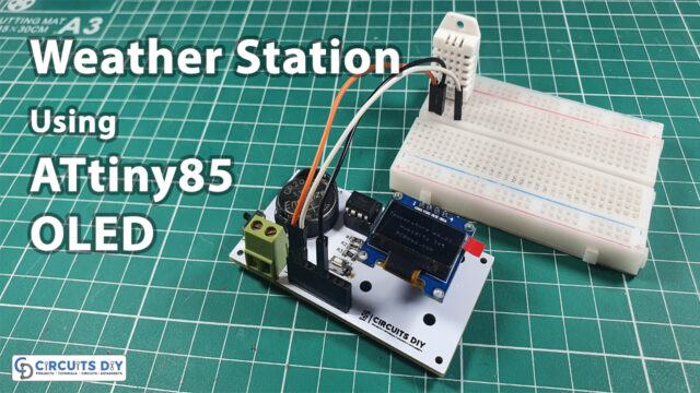
Introduction
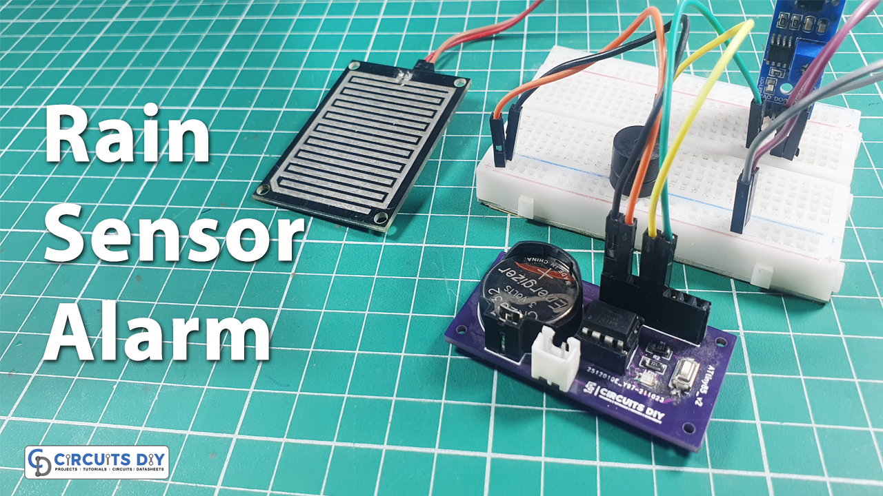
The weather has been known to be unpredictable. Although, rain is a source of affection for humans and soothes the soul of a person. But sometimes unpleasant things happen if we get no alert. As a result, it may put a lot of things at risk. Therefore the rain sensor was created so that people can get notified when it rains. It is also found in electrical shutters and windows. This sensor is also used in the automotive industry for car applications, among other things. Therefore in this article, we are going to make. Rain Detection Alarm System using AtTiny85.
An Overview of Rain Sensor
The sensor’s detecting pad is primarily made up of copper traces. The variable resistor is made up of these traces. As a result, the resistance varies depending on how much water is on the surface. Higher conductivity equals lower resistance, hence more water implies lower resistance. Lesser water content means lower conductivity, which equals higher resistance. As a result, this resistance dictates the voltage, which aids in the prediction of rain
PCBWay commits to meeting the needs of its customers from different industries in terms of quality, delivery, cost-effectiveness, and any other demanding requests. As one of the most experienced PCB manufacturers in China. They have an open-source community, people can share their design projects with each other. Moreover, every time people place an order for your board, PCBWay will donate 10% of the cost of PCB to you, for your contribution to the Open Source Community.
Hardware Components
The following components are required to make Rain Detection Alarm Circuit
ATTiny85 Pinout
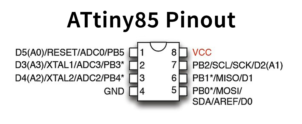
For a detailed description of pinout, dimension features, and specifications download the datasheet of ATTiny85
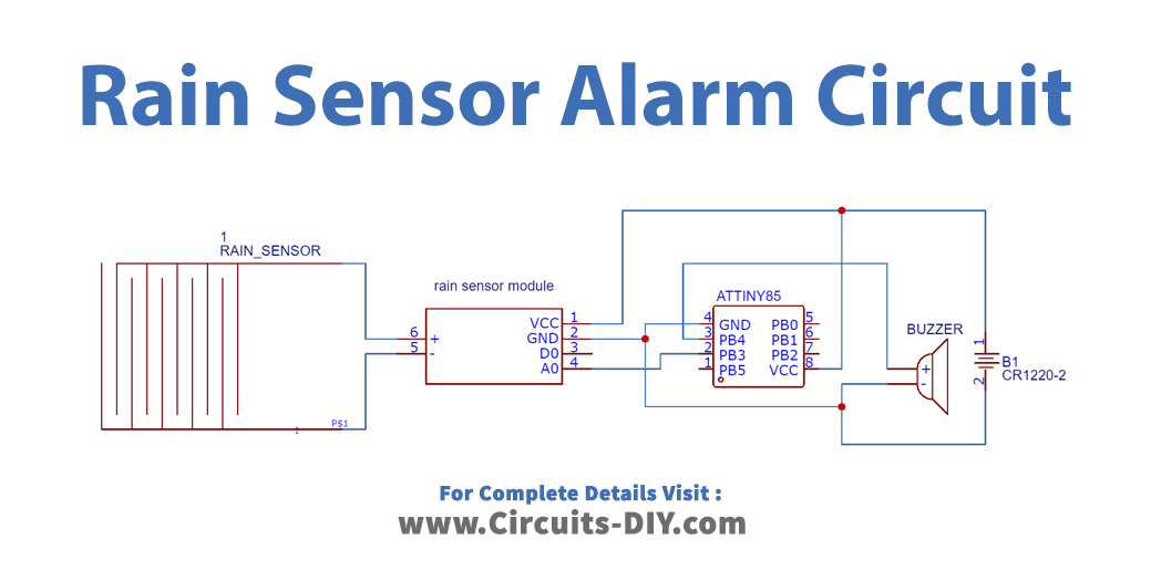
Rain Detection Alarm Circuit
Arduino Code
void setup() {
  //Serial.begin(9600);//enable serial monitor
  pinMode(4, OUTPUT);//define LED pin
}
void loop() {
  int value = analogRead(A3);//read value
  //Serial.print1n("Value : ");
  //Serial.println(value);
  if (value < 300) {//check condition
    digitalWrite(4, HIGH);
   //Serial.print1n("Heavy rain  LED on ");
  } else {
    digitalWrite(4, LOW);
  }
}
Working Explanation
Connect the circuit, and burn the code in Attiny85 IC. The sensor takes the reading in a way that when there is no rain, the resistance is lower. Therefore the output voltage is higher. This, LED turns ON, and the serial monitor shows the message. When the raindrop appears on the sensor, the resistance gets higher. And, the output voltage gets lower.
Code Explanation
- In the void setup, we initialize the serial monitor by giving the Serial.print function. Then, we have defined pin 4 of an Arduino as the output pin, to which an LED is connected.
- In the void loop, we have defined the variable value that stores an integer value coming from the sensor. To get the analog readings from the sensor, we have given the analogRead function. Then, we print the value by using Serial.println. After that, we give the if condition in which when the value gets greater than 300, the sensor will get the LED ON, and print, Heavy rain LED on. Otherwise, the output pin remains Low.
Applications and Uses
- The circuit can be employed in weather stations.
- Farming and agriculture devices, irrigation systems
- In-home automation systems.
- They are used in automobile wipers.