Today, we are fabricating here an astounding RGB bulb utilizing Red, Green, and Blue LEDs. Meanwhile, we simply need to add a small circuitry mechanism to control the intensity of these LED lights independently. Therefore, to control the splendor, we are utilizing the PWM (Pulse width Modulation) technique with a 555 timer IC. Hence, the 555 timer IC can produce a voltage pulse of variable width, and the width of the Pulse can control the Duty cycle.
The higher the duty cycle, the higher will be the brightness or intensity of the LED. Subsequently, the lower the duty cycle, the Lower will be the LED Brightness. For instance, the HIGH time for this circuit is approximately 8ms and the LOW time is approximately 2ms. Additionally, at that point when the duty cycle is at 80%, it implies the LED is wavering between ON (8ms) and OFF (2ms). Therefore, our eyes can’t see such high-frequency motions and it consequently Looks like LED is consistently ON at the brightness of 80%.
Hardware Components
The following components are required to make RGB LED Bulb Circuit
| S.no | Component | Value | Qty |
|---|---|---|---|
| 1. | IC | NE555 Timer | 3 |
| 2. | Resistor | 1K, 220 ohm | 3, 3 |
| 4. | Variable Resistor | 10K | 3 |
| 5. | Capacitor | 0.1uF, 0.01uF | 3, 3 |
| 7. | Diode | – | 6 |
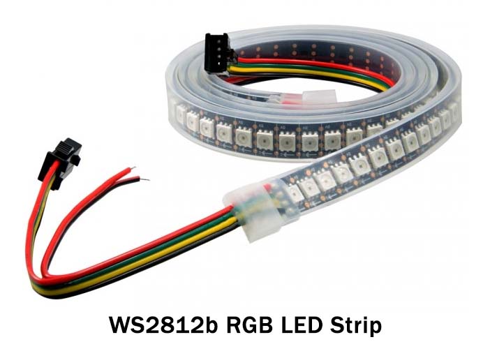
| 8. | LEDs | – | 3 |
| 9. | Battery | 5-9 V | 1 |
NE555 IC Pinout

For a detailed description of pinout, dimension features, and specifications download the datasheet of 555 Timer
RGB LED Bulb Circuit

Working Explanation
The circuit is straightforward, 555 timers are arranged here in Astable Mode. Meanwhile, the frequency and duty cycle are reliant upon the resistors between PIN 8 and 7 and subsequently PIN 7 and 6 and the timing capacitor C1.
We have associated a variable resistor between PIN 6 and 7, with two diodes, so the capacitor C1 is charged through one piece of the variable resistor and released utilizing another piece of the variable resistor.
For instance, we have set the variable resistor (10k) handle like that resistor is partitioned somewhere in the range of 7k and 3k, so the capacitor will be charged through the 7k resistor and released through the 3k resistor.
Furthermore, the yield is High when the capacitor is charging and Low when the capacitor is discharging. so for this situation, the HIGH time is more prominent than the LOW time and the subsequent duty cycle is additionally more noteworthy, so LED will be more bright.
Furthermore, on the off chance that we pivot the knob the opposite way, that will make the LED dimmer. So by turning the knob of the Potentiometer we can control the brightness of the LED. A similar circuitry mechanism is applied for the other two LEDs (RED and GREEN).
Applications and Uses
There are a lot of DIY Home LED Applications. Some of them are:
- Home
- Shops
- Office
- Indoor and outdoor lighting etc