IR sensor is a famous electronic sensor, which is widely utilized in numerous applications in electronic hardware. Likewise, it utilizes Remote control systems, movement identifier or motion detector systems, Product counter, Line following Robots, Alarms, and so on. IR Sensor fundamentally comprises an IR LED and a Photodiode.
In this circuit, we will exhibit an application of IR sensors which is known as “IR Detector”. We have made this circuit by utilizing the 555 Timer IC. Moreover, here we are utilizing an IR LED or TV/DVD remote as an IR transmitter and Photodiode as IR Receiver to distinguish the IR signal. Recognition of the IR signal will Trigger the 555 timers, subsequently, the buzzer will begin blaring. Practically the same idea has just been shrouded in our past circuit tutorials: IR Based Security Alarm, where we utilized voltage comparator IC LM358 to trigger the 555 IC.

Hardware Components
The following components are required to make IR Detector Circuit
| S.no | Component | Value | Qty |
|---|---|---|---|
| 1. | Breadboard | – | 1 |
| 2. | Resistor | 1K, 10K, 22K, 220 ohms | 1 |
| 3. | Electrolytic Capacitor | 10uF | 1 |
| 4. | IC | NE555 Timer | 1 |
| 5. | Transistor | BC547, BC557 | 1 |
| 6. | Power supply | 5V | 1 |
| 7. | LED | – | 1 |
| 8. | Buzzer | – | 1 |
| 9. | IR LED or TV/DVD Remote | – | 1 |
| 10. | IR receiver or Photodiode | – | 1 |
NE555 IC Pinout

For a detailed description of pinout, dimension features, and specifications download the datasheet of 555 Timer
BC547 Pinout

For a detailed description of pinout, dimension features, and specifications download the datasheet of BC547
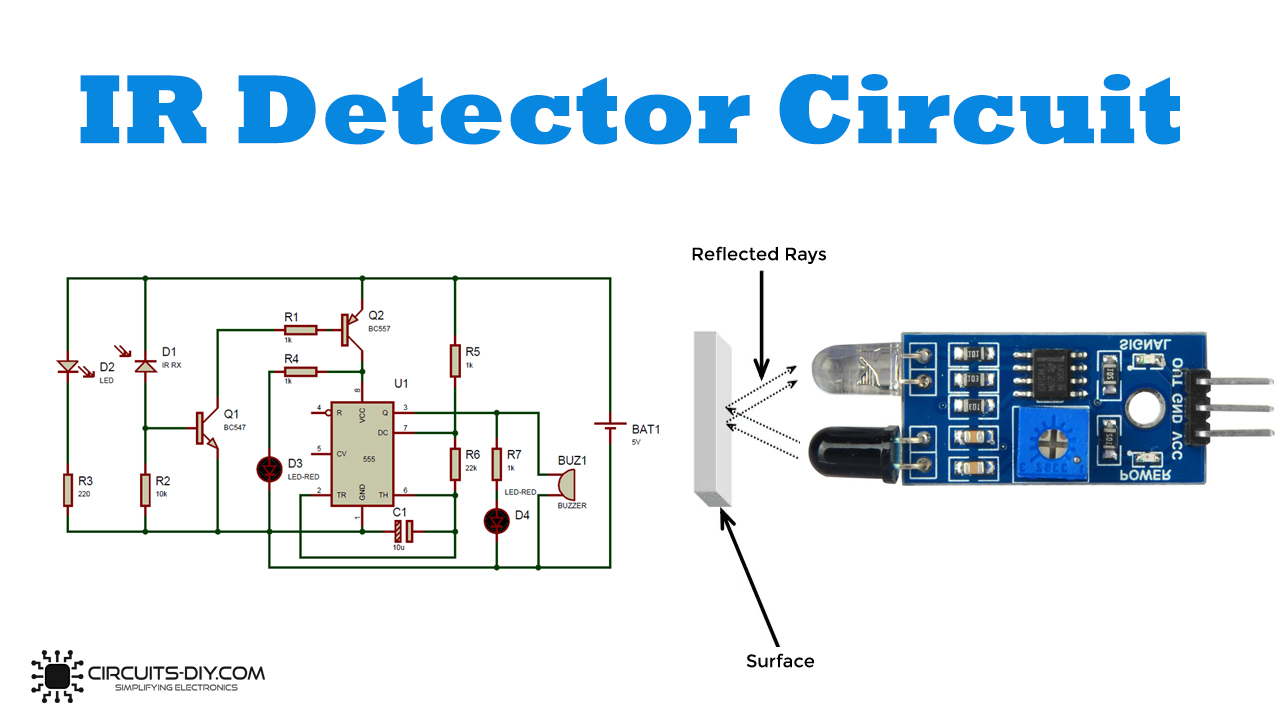
IR Detector Circuit
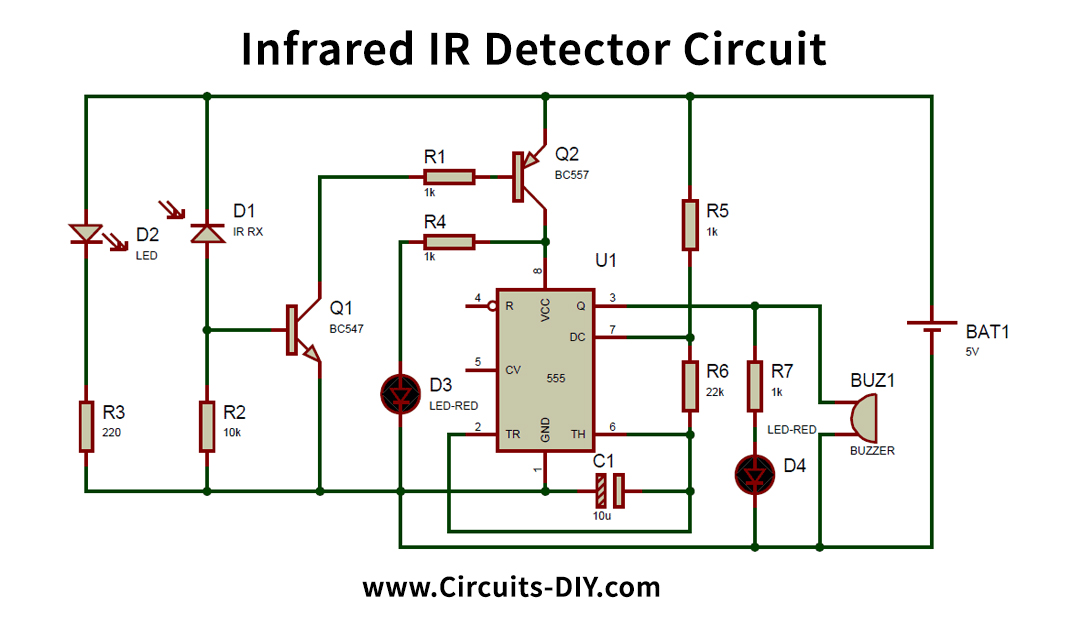
Working Explanation
At the point when the IR Sensor Circuit is turned ON, IR LED begins emanating the Infrared, which falls upon the photodiode and a voltage difference is created across the photodiode which Turns On the semiconductor BC547. However, it further Turns On the Transistor BC557 by triggering its base to the Ground. Therefore, the Transistor BC557 begins directing and the power supply is applied to the 555 Timer IC (at PIN 8), which turns ON the 555 IC. 555 Timer IC is designed in Astable Mode, so the LED and signal, which are associated with its Output (PIN 3), begin flickering and blaring, with a specific frequency. This frequency of LED flickering can be controlled by the given formulae of the Astable Multivibrator:
F = 1.44/(R1+2*R2) * C1
Where R1 refers to the resistor between Pin 7 and Pin 8 and R2 refers to the resistor between Pin 6 and Pin 7. C1 is a capacitor between Pin 6 and Ground of 555 Timer IC. Where R is in ohm and C (capacitance) is in farads.
We can likewise utilize a TV/DVD remote for IR radiation (supplanting the IR LED). Meanwhile, the 555 Timer IC is here producing some proportional frequency. The 555 Timer IC is a universally useful IC that can be arranged in various modes like A-steady, Mono-stable, and Bi-stable, having various applications for every mode. Here in this task, we have designed 555 Timer as an A-stable multi-vibrator in which both the phase of the signal are precarious.
To distinguish or peruse the IR light, we can likewise utilize TSOP1738 as IR Receiver, its yield is dynamic low, implies yield stays High when there is no IR, and turns out to be low when it identifies IR, you can check IR Transmitter and Receiver utilizing TSOP.
Applications and Uses
- Use to interpret the IR signals sent from a remote control.