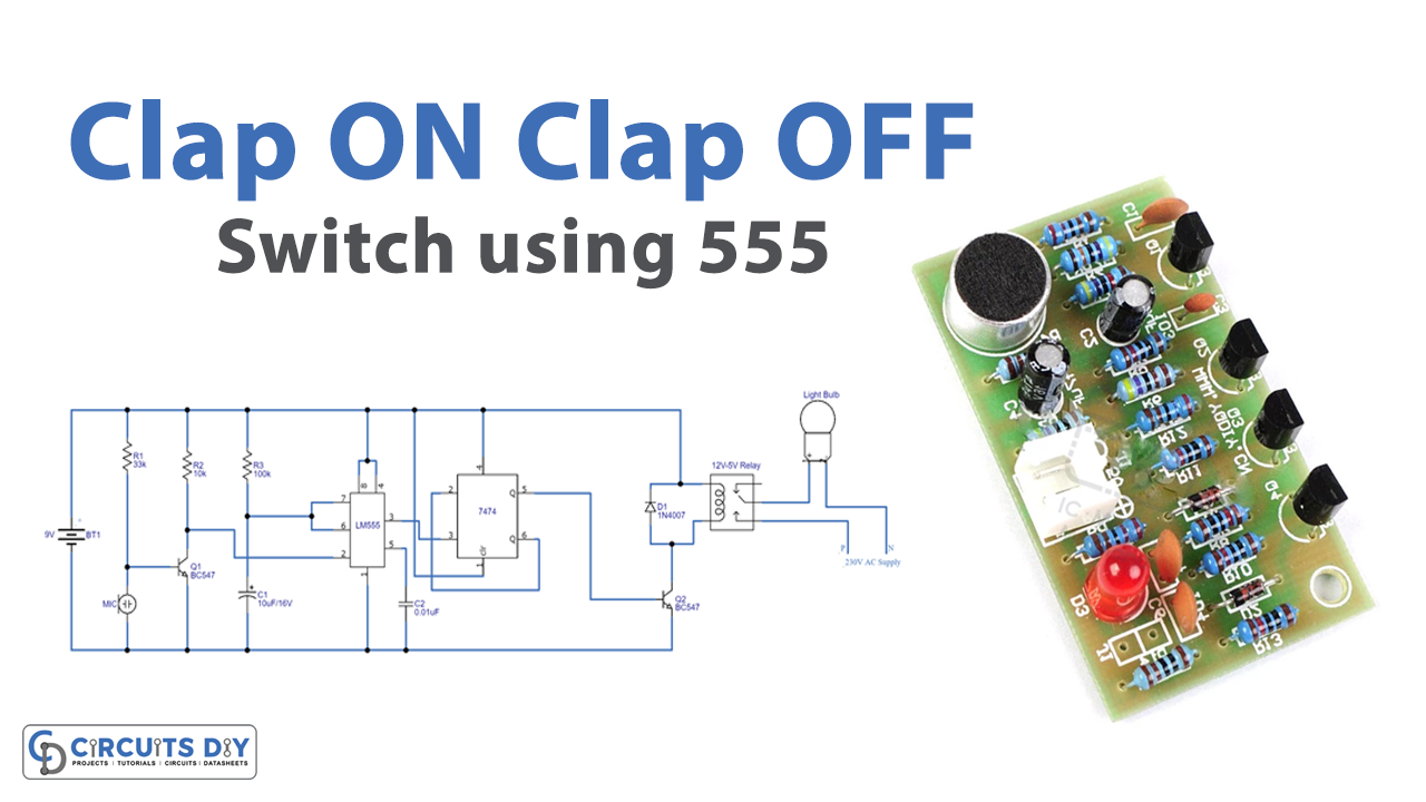
In this tutorial, we are going to make a “Clap ON Clap OFF Switch using 555 Circuit”.
A “Clap On Clap Off” switch makes devices On and Off by making a clap sound that makes it use full for home automation. When you clap the load is switched ON again when you clap the load is switched OFF, which means this circuit switch any appliance by detecting the sound. Just as remote access to electrical devices is making us comfortable and it can also be very convenient if you can control an electric device with Clap. Here we design a simple clap ON clap OFF switch using a 555 timer and this circuit can help us to control the electric bulb. In this circuit 555 timer IC, and 7474 dual positive edge-triggered D-type flip flop is used and an electric condenser Mic, is working as a sound sensor. Condenser Mic converts sound energy into electrical energy, that in turn is used to trigger 555 timer IC and the relay device control high volt electric appliances.
Hardware Required
| S.no | Component | Value | Qty |
|---|---|---|---|
| 1. | IC | 7474 | 1 |
| 2 | Timer IC | LM555 | 1 |
| 3. | NPN Transistor | BC547 | 2 |
| 4. | Relay | 9V | 1 |
| 5. | Condenser Mic | – | 1 |
| 6. | Resistor | 33KΩ, 1KΩ, 100KΩ | 1, 1, 1 |
| 7. | Capacitor | – | 1, 1 |
| 8. | Diode | 1N4007 | 1 |
| 9. | Bulb | – | 1 |
| 10. | Battery | 9V | 1 |
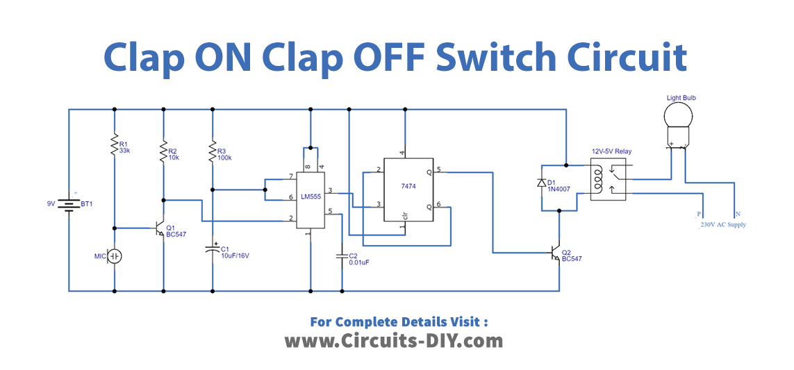
Circuit Diagram
Working Explanation
This circuit has two stages, which are the clap detecting & trigger stage and the switching stage. The first one is consisting of a condenser microphone and a 555 timer that is configured as a monostable multivibrator, whose output (PIN 3 of 555 IC) has been used as a clock pulse. Here Mic output is connected with the timer IC’s trigger Input (the pulse output from the timer is monopulse, and the duration of this pulse depends on timer elements R3 and C1 values) then output from the timer IC is connected with the clock input of D flip flop. The D flip flop detects a positive edge in the pulse and changes its state accordingly. D flip flop output is connected to the Q2 transistor base and this transistor makes the relay coil ON or OFF.
Now when we produce some sound near condenser MIC such as a clap sound occurs, this sound will be converted into electrical energy and it will raise the potential at the base, which will turn the transistor Q1 ON. As soon as the transistor becomes ON, the potential would become low and this will trigger timer IC then mono pulse produced because of the low voltage (below Vcc/3) at Trigger Pin 2. So, the output PIN3 will be high and a positive clock pulse will be applied to flip flop clock input, which makes Flip-flop respond, and LED will turn ON. Here the flip flop detects the positive edge of the pulse and changes its state to either ON or OFF depending on the current state. The SET state of the flip flop will remain ON until the next clock pulse means until the next Clap/sound. So, this is the clap switch that will turn ON with the first clap and turn OFF with the second clap.
Applications
- This circuit will help us to switch On the lights in the dark when we can’t locate the switchboard.
- When using this circuit, there is no fear of electric shock as you don’t have to touch any mechanical switches physically