Introduction
Relays play an important role in automation circuits. Whether it’s industrial or home, the type of relays can change but the principle remains the same. You may already know that relays in home automation are devices that activate another appliance. This might be anything from a light bulb to a motor. Smart home automation can be used in a variety of settings to improve the connectivity of your house. In other words, Smart Relays have installed devices that can be added to any electrical circuit and allow remote wireless control of anything else connected to that circuit. But what, if we make those smart relays IoT-friendly? Does this grab your attention? If yes, then read the entire article. Because in this tutorial, we are going to make a “Smart IoT Relay Module”.
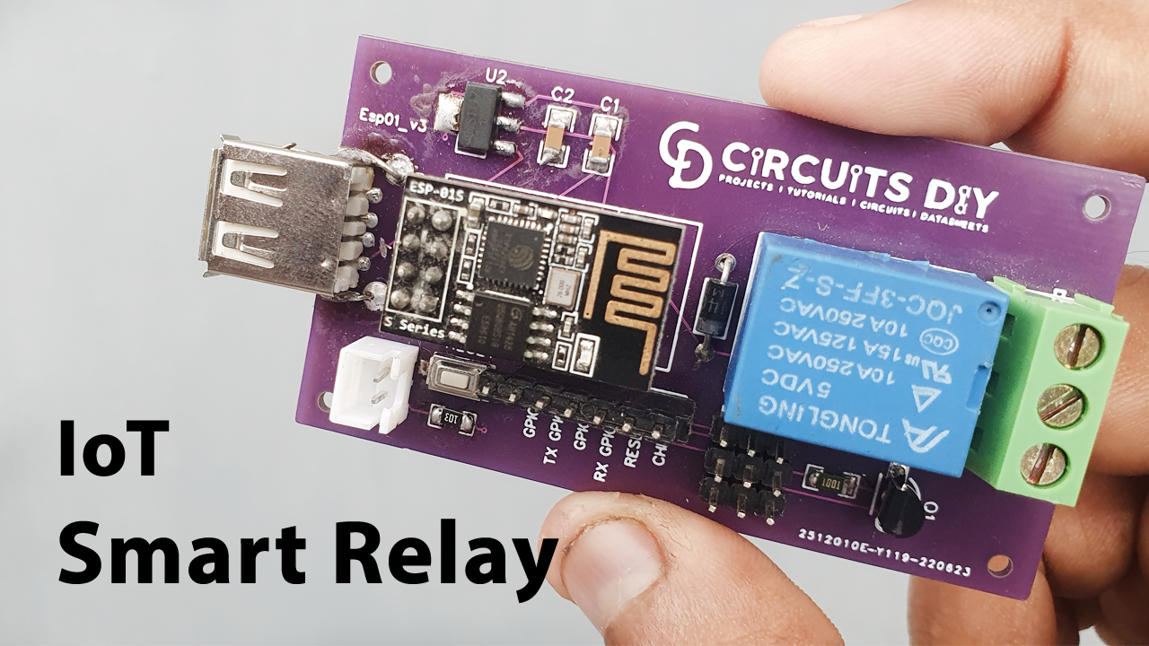
In the making of this tiny circuit, we are utilizing ESP8266-01 which will allow access to the wi-fi network in the circuit. As a result, we can control a relay through the Internet.
This Project is sponsored by PCBWay. They have an open-source community, people can share their design projects with each other. Moreover, every time people place an order for your board, PCBWay will donate 10% of the cost of PCB to you, for your contribution to the Open Source Community.
Hardware Required
| S.No | Component | Value | Qty |
|---|---|---|---|
| 1) | ESP8266 ESP01 | – | 1 |
| 2) | Voltage Regulator | AMS1117 3.3V | 1 |
| 3) | SMD Resistors | 10K, 1K | 1,1 |
| 4) | Push Button SMD | – | 1 |
| 5) | Relay | 5V | 1 |
ESP8266-01 Code
#include <ESP8266WiFi.h>

const char* ssid = "Circuits DIY";
const char* password = "03433212601";
int RelayPin = 2; // GPIO2
WiFiServer server(80);

void setup()
{
Serial.begin(115200);
delay(10);
pinMode(RelayPin, OUTPUT);
digitalWrite(RelayPin, LOW);

// Connect to WiFi network

Serial.println();
Serial.println();
Serial.print("Connecting to ");
Serial.println(ssid);
WiFi.begin(ssid, password);

while (WiFi.status() != WL_CONNECTED) {
 delay(500);
 Serial.print(".");
 }
 Serial.println("");
 Serial.println("WiFi connected");
  // Start the server
  server.begin();
  Serial.println("Server started");
  // Print the IP address
  Serial.print("Use this URL to connect: ");
  Serial.print("http://");
  Serial.print(WiFi.localIP());
  Serial.println("/");
}

void loop() {

  // Check if a client has connected
  WiFiClient client = server.available();
  if (!client) {
    return;
  }

  // Wait until the client sends some data
  Serial.println("new client");
  while(!client.available()){
  delay(1);
  }

  // Read the first line of the request
  String request = client.readStringUntil('\r');
  Serial.println(request);
  client.flush();

  // Match the request
  int value = LOW;

  if (request.indexOf("/RELAY=ON") != -1)  {
    digitalWrite(RelayPin, LOW);
    value = LOW;
  }
  if (request.indexOf("/RELAY=OFF") != -1)  {
    digitalWrite(RelayPin, HIGH);
    value = HIGH;
  }

  // Return the response
  client.println("HTTP/1.1 200 OK");
  client.println("Content-Type: text/html");
  client.println(""); //  do not forget this one
  client.println("<!DOCTYPE HTML>");
  client.println("<html>");
  client.println("<h1>IoT Smart Relay</h1>");
  client.println("<h4>www.Circuits-DIY.com</h4>");
  client.println("<img src=\"https://static.thenounproject.com/png/731364-200.png\">");
  client.println("<br>");

  client.print("Relay Pin is now: ");
  if(value == LOW) {
    client.print("On");
  } else {
    client.print("Off");
  }
  client.println("<br><br>");
  client.println("<a href=\"/RELAY=ON\"\"><button>Turn On </button></a>");
  client.println("<a href=\"/RELAY=OFF\"\"><button>Turn Off </button></a><br />");
  client.println("</html>");
  delay(1);
  Serial.println("Client disonnected");
  Serial.println("");
}
Smart Relay Circuit

Steps to Install ESP8266 NodeMcu In Arduino IDE
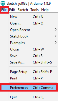
- Navigate to File> Preferences in your Arduino IDE.
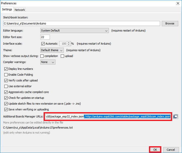
- As indicated in the picture below, enter http://arduino.esp8266.com/stable/package esp8266com index.json into the “Additional Boards Manager URLs” section. Then press the “OK” button. If you already have the URL for the ESP32 board, separate the Links with a comma.
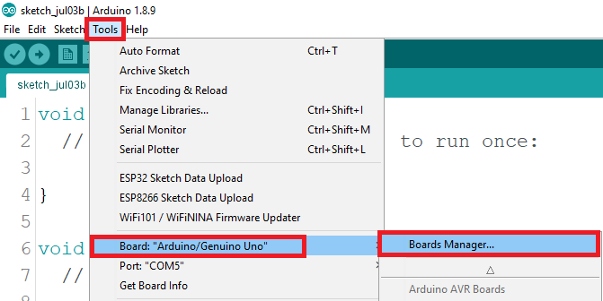
- Navigate to Tools > Boards Manager.
- Search for ESP8266 and click the “ESP8266 by ESP8266 Community” install button.
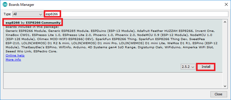
- That’s all. Within a few seconds, it will be installed.
Uploading the Code
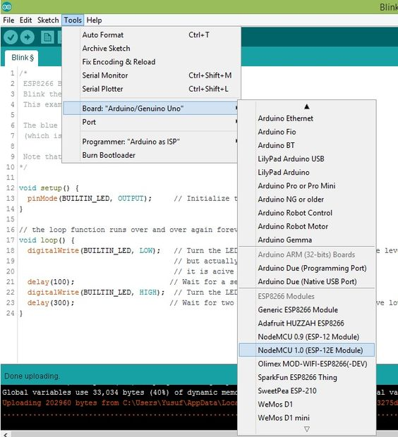
- Because it includes a built-in programmer, posting the sketch is quite straightforward. Connect the board to your computer. Check that you have the correct board chosen.
- You must also pick the correct Port.
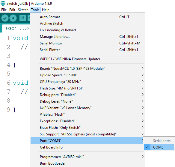
- In the Arduino IDE, click the “Upload” button and wait a few seconds until you get the message “Done uploading.” in the lower left corner.
Working Explanation
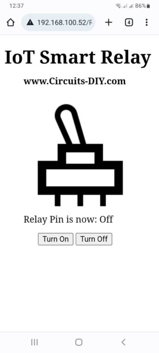
Here’s the circuit’s fundamental operating concept: Using a relay module and the application, we can turn on or off a bulb. After you make the connections properly, upload the code, and then open the Serial monitor. Next, simply copy and paste the provided IP into your phone’s or system’s browser. The application is now available for you to use.
Code Explanation
- First, we have included the libraries for the ESP8266 module. Then define our SSID and password. A char* is a char pointer. WiFiServer(80); This method establishes a server that waits for incoming connections on the given port. The default HTTP port is 80, and the web server is on port 80 here.
- In void setup, WiFi.begin establishes the network settings for the WiFi library and gives the status right away. WiFi.status() Return the connection status. WL_CONNECTED assigned when connected to a WiFi network.
- we give the condition to quit early if any reading failed. WiFiClient client. creates a client that has the connection to a client-defined internet IP address.
Application and Uses
- Lighting control
- Lawn irrigation
- Kitchen appliances
- And, security systems