
Introduction:
Almost all the industrial sector works with heavy machinery and crucial mechanical and electrical devices which are sensitive to be handled and a minor mishandling or technical issue can cost several lives and a severe loss of money. These types of industries or gas stations use proper alarm systems for emergencies. The fire alarm system is one of the crucial needs in these kinds of industrial sector, but the residential and commercial sector also utilizes such systems to ensure safety.
A fire alarm system is designed to aware people of fire, smoke, carbon monoxide, or any other emergency so that necessary action can be taken. The major component of the circuit is the temperature sensing element such as a thermistor which is a temperature sensing resistor and changes resistance according to the temperature. The resistance is inversely proportional to the temperature.
Here we have built a circuit using a thermistor, 555 timer IC, NPN transistor, and a few other components to operate.

Hardware Components
The following components are required to make a Fire Alarm Circuit
| S.no | Component | Value | Qty |
|---|---|---|---|
| 1. | IC | NE555 Timer | 1 |
| 2. | Thermistor | 103 NTC | 1 |
| 3. | Buzzer | 5V | 1 |
| 4. | Transistor | BC547 | 1 |
| 5. | Variable Resistor | 100KΩ | 1 |
| 6. | Resistor | 100KΩ, 1KΩ, 4.3KΩ, 10Ω | 2, 1, 1, 1 |
| 7. | Capacitor | 10μF / 16V, 0.01μF | 1 |
| 8. | Battery | 9V | 1 |
NE555 IC Pinout

For a detailed description of pinout, dimension features, and specifications download the datasheet of 555 Timer
Fire Alarm Circuit
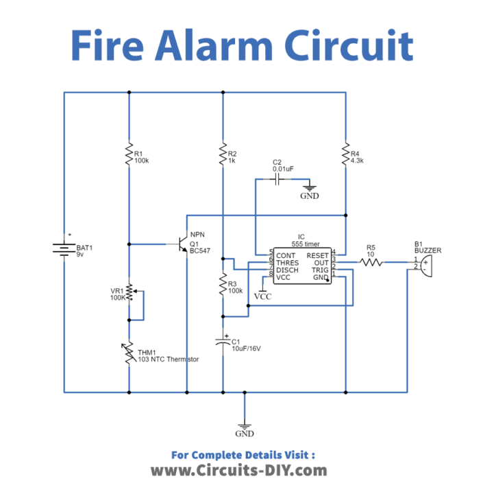
Construction & Working:
In this circuit, 555 IC is configured in the astable mode for a buzzer to generate sound oscillations. In this mode of operation, the capacitor C1 charges through the resistors R2 and R3 up to the 2/3 value of VCC, and during this time the Pin3 remains high while the capacitor discharges up to 1/3 of the VCC through the resistor R3 and the Pin3, during this time remains low. This function of Pin3 produces oscillations hence the sound of the buzzer is generated in oscillations.
As the power supply is applied to the circuit, the transistor is in the ON state due to the voltage at the base-emitter junction which means the Pin4 (reset) of the IC is grounded and hence IC does not operate. When the thermistor senses the heat its resistance decreases which decrease voltage across the base-emitter junction and as the voltage reduces below the operating range of transistors it goes into the OFF state and the reset pin of the IC gets positive voltage through the resistor R3 which makes the IC operate, and the buzzer starts to beep.
Application:
The various applications of fire alarm circuits are as follows:
- It is used in factories and industries.
- It is used in commercial and residential buildings to ensure safety.
- It is applicable in banks and data centres.
- Furthermore, it is also applicable in gas stations.
- Hence, a large sector utilizes this system for safety purposes and to avoid any disaster.