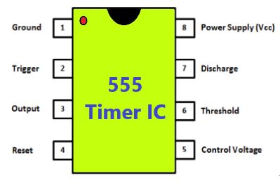
The 555 timer IC was developed by Signetic Corporation in the year 1970. It is basically a monolithic timing circuit that produces accurate and highly stable time delays and it is used in many applications like dc-dc converters, waveform generators, and voltage regulators. This IC released in two parts: NE 555 and SE 555. The NE 555 parts are for commercial usage with a temperature range of 0°C to 70°C similarly, the parts of SE 555 parts are designed for military applications with a temperature range of -55°C to 125°C.
Operating Modes
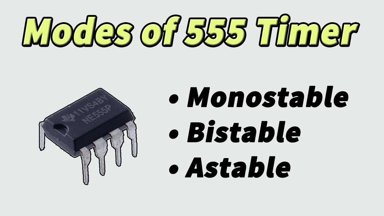
The 555 timer IC can be operated in three modes: astable, bistable and monostable. Each mode of operation has a separate circuit diagram and the output also varies.
Monostable Mode
In this mode, the circuit produces only a single pulse in response to a trigger input such as a push button. The word “monostable” means one stable state hence the output will always stay in a low state until there is a trigger input. The duration of the pulse depends on the values of the capacitor and the resistor
Bistable Mode
The 555 timer in bistable mode has two stable states, High and Low. It is similar to a flip flop circuit which alternates between two stable states. Unlike the astable mode and monostable mode, the timing of the circuit in bistable mode is not controlled by a capacitor and resistor. Instead, the output is controlled directly by the Reset and Trigger input pins.
Astable Mode
In this mode, the 555 timer has no stable state and acts as an oscillator that generates a square wave. The output continuously switches between high and low without any human intervention. The frequency of the pulse depends on the values of resistors and capacitors used in the circuit and in order to obtain long time delays, resistors and capacitors of higher values are used. This circuit is mostly used as a ‘clock’ pulse for other digital ICs and circuits.