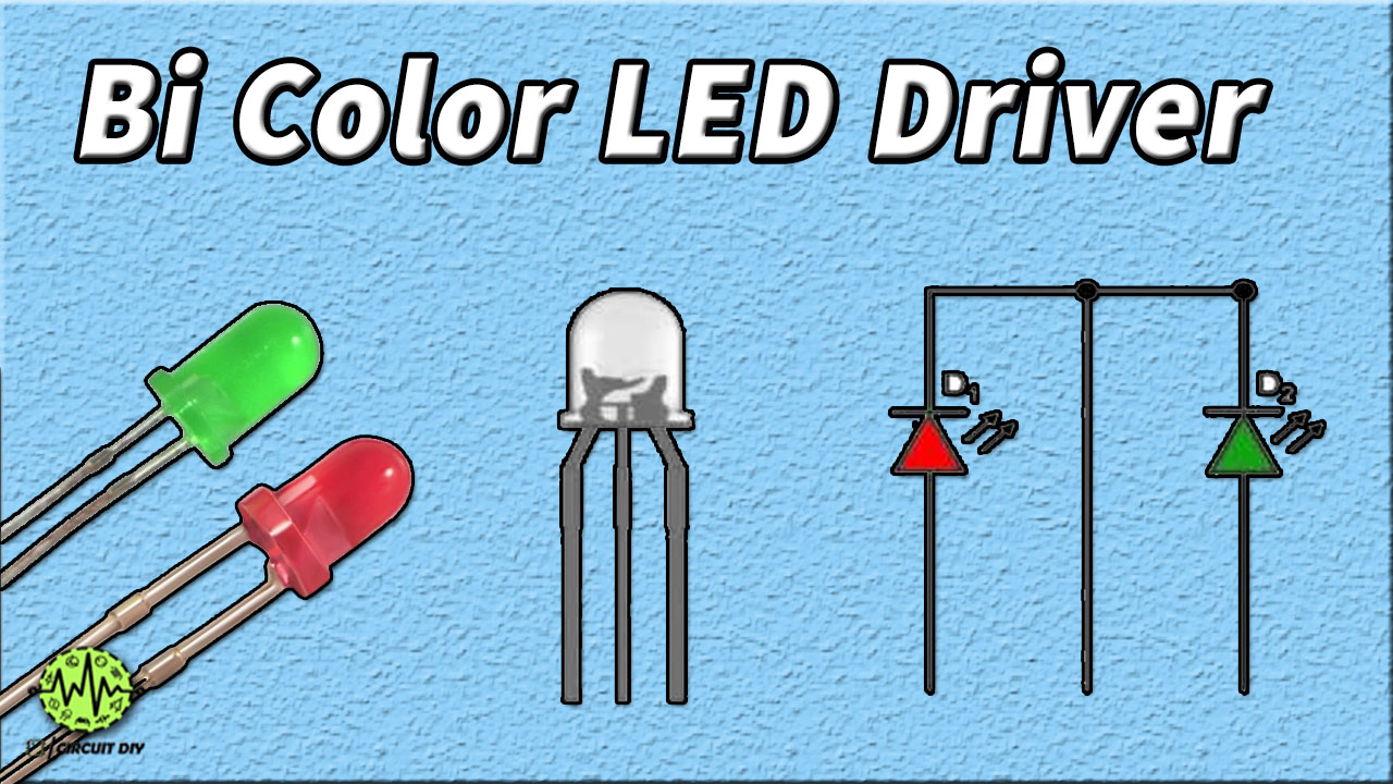
In this tutorial, we will show you how to make a Bi-Color LED Driver Circuit using a 555 timer IC. A Bi-color LED consists of three terminals- one common pin and two separate pins (one for each color). The LED used in this circuit produces 2 colors: Red and Green. We can connect the common pin to the ground if the LED is a common cathode or we can connect the common pin to +5V if we are using a common anode LED.

Hardware Components
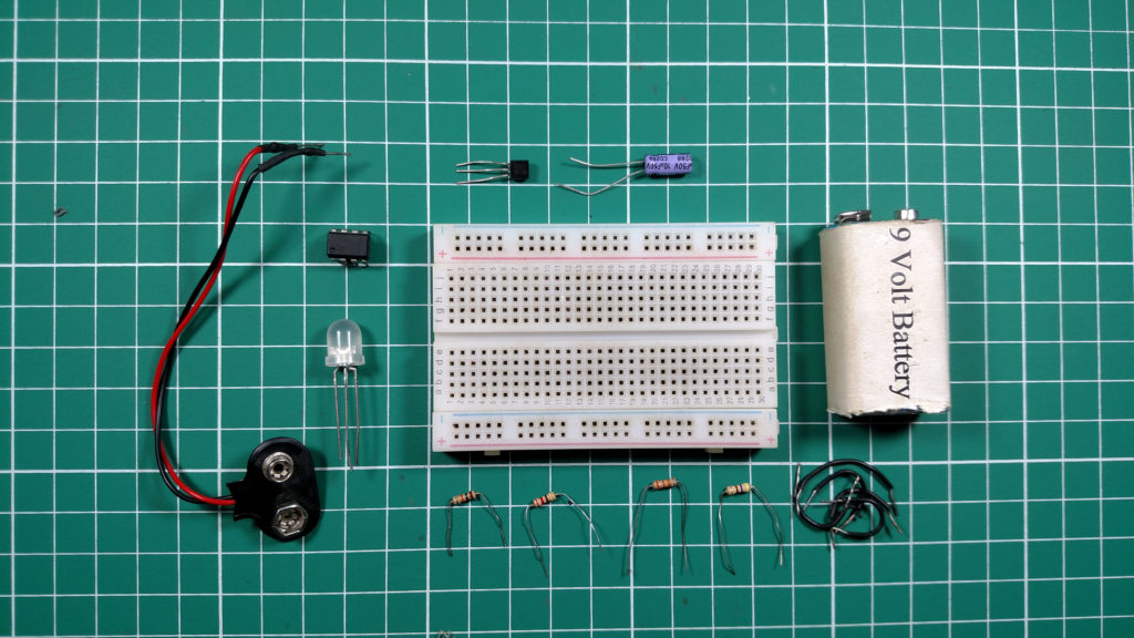
The following components are required to make Bi-Color LED Driver Circuit
| S. NO | Component | Value | Qty |
|---|---|---|---|
| 1. | Breadboard | – | 1 |
| 2. | Battery | 9v | 1 |
| 3. | Connecting Wires | – | 1 |
| 4. | IC | NE555 Timer | 1 |
| 5. | PNP Transistor | BC557 | 1 |
| 6. | Bi-Color LED | – | 1 |
| 7. | Electrolytic Capacitor | 10uF | 1 |
| 8. | Resistors | 33k, 10k, 4.7k, 220 ohms | 1,1,1,1 |
555 IC Pinout

For a detailed description of pinout, dimension features, and specifications download the datasheet of 555 Timer
Circuit Diagram
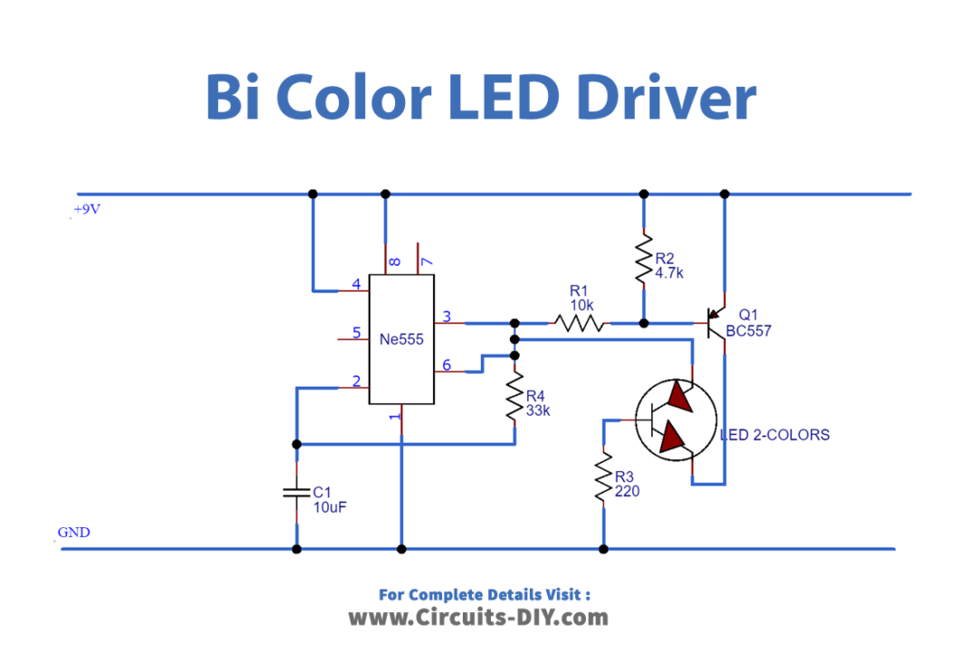
Connections
- Connect Pin 4 & Pin 8 To VCC.
- Use a jumper wire to connect Pin 6 & Pin 2 together.
- Connect Pin 1 to GND.
- Add a 10uF capacitor between Pin 2 and GND.
- Use a 10K Ω resistor to connect Pin 3 to the Base of the transistor.
- Connect a 4.7K Ω resistor between the Base of the transistor & VCC.
- Add a 33K Ω resistor between Pin 3 and Pin 6.
- Connect the Emitter of the transistor to VCC.
- Connect LED as shown in the circuit diagram.
Working Explanation
A Bipolar LED consists of two diodes connected in opposite directions to each other. The functioning of the LED depends upon the positive signal given to one of the terminals. For example, if we are using a green and red color bi-polar LED then a positive signal applied at the red terminal and a negative signal applied at the green terminal ensures that the red LED is forward biased. This causes the red LED to glow while the green LED remains off. Similarly, if we give a positive signal to both the terminals of LED, a color depending upon the combination of both colors will flash.
We are using 555 timer IC in the astable mode for this project. Output pin 3 is connected to the two terminals of the LED. One of the terminals of the LED is receiving output through a PNP transistor which turns on when the output of the 555 timers is Low. The second LED terminal is directly connected to the output pin of the 555 timers and it turns on when the output of the 555 timers is High.
Applications
- Bi-color LED is used in two-color indicator lamps, avoiding the need for two LEDs of different colors.
- We can use this circuit for indication purposes.