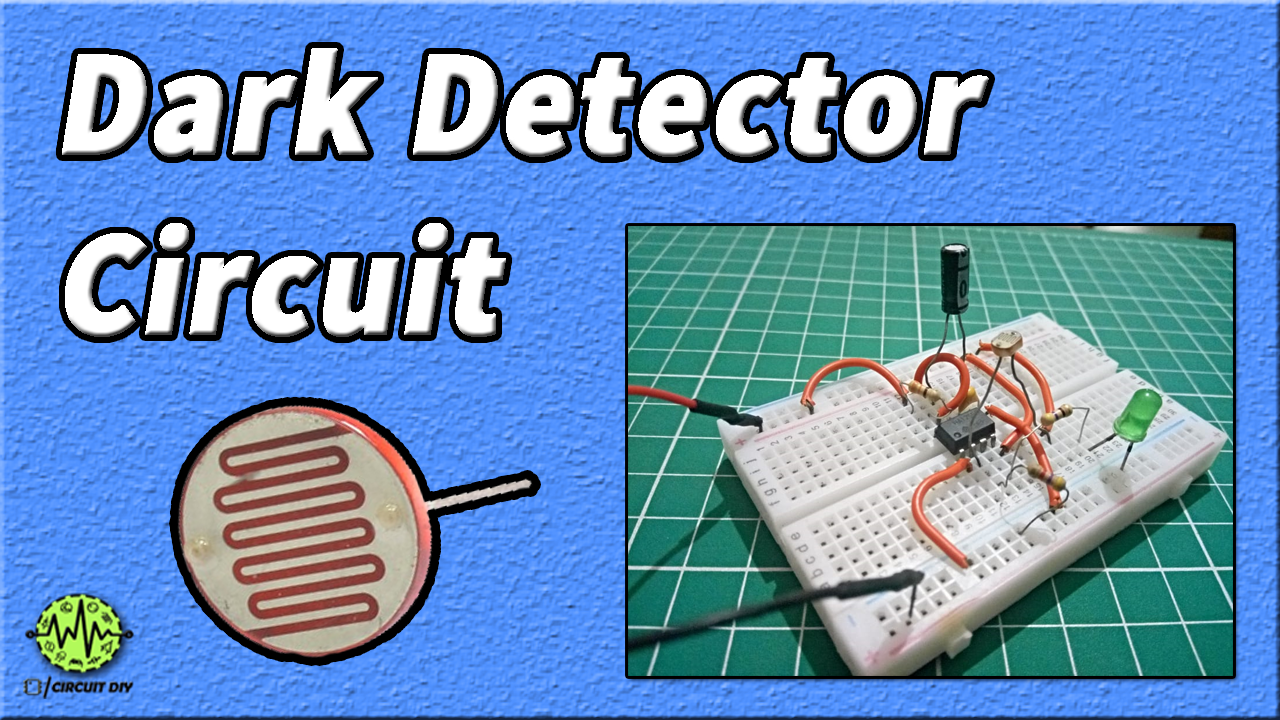
A dark detector circuit is used to detect the darkness OR absence of light in any area. It can be used in applications where we can automatically turn on lights when it becomes dark Automatic Street Light is the best example of it. The dark detector circuit consists of LDR (Light Dependent Resistor) when light falls on it its resistance starts to increase and due to this our biased transistor turns on the LED.

Hardware Components
The following components are required to make Dark Detector Circuit
| S. NO | Component | Value | Qty |
|---|---|---|---|
| 1. | Breadboard | – | 1 |
| 2. | Connecting Wires | – | – |
| 3. | Battery | 9v | 1 |
| 4. | IC | NE555 Timer | 1 |
| 5. | Ceramic Capacitor | 100nF | 1 |
| 6. | Electrolyte Capacitor | 100uF | 1 |
| 7. | Resistors | 330 ohm, 470 ohms, 4.7K | 1, 1, 1 |
| 8. | LDR | – | 1 |
555 Timer Pinout

For a detailed description of pinout, dimension features, and specifications download the datasheet of 555 Timer
Useful Steps
Follow All Steps Carefully from the Video Tutorial Above (Recommended)
- STEP # 1 ( Connect IC )
- Connect 555 timer IC on the breadboard
- STEP # 2 ( Make power connections )
- Pin 8 of 555 Timer – To VCC of Battery
Pin 1 of 555 Timer – To GND of Battery - STEP # 3
- Connect pin 4 to VCC
Connect wire BTW pin 6 and pin 7 - STEP # 4 ( Connect resistor #1 )
- Connect 330-ohm resistor BTW pin 7 and pin 8 of IC
- STEP # 5 ( Connect capacitor #1 )
- Connect 100uf capacitor to pin 5 of IC
- STEP # 6 ( Connect capacitor #2 )
- Connect 100nf ceramic capacitor on pin 6 of IC
- STEP # 7 ( Connect resistor #2)
- Connect 4.7k ohm resistor on pin 2 of IC
- STEP # 8 ( Connect LDR )
- Connect LDR BTW pin 2 and VCC
- STEP # 9 ( Connect resistor #3 and LED )
- Connect 470-ohm resistor and LED BTW pin 3
- STEP # 10 ( Testing )
Dark Detector Circuit Diagram

Working Explanation
when the darkness falls on the LDR, the resistance of the LDR increases, this increase of resistance in the second branch of the voltage divider will be enough to change the ratio of voltage sharing between the two branches of the voltage divider section. Once this happens, the potential at the junction of the voltage divider circuit rises from 0V to 2V. And similarly, the voltage at the RESET pin rises. This rise in voltage will be enough to lift the 555IC from reset mode. Once this reset mode is lifted, the timer generates a square wave output. The square wave generated by the timer triggers the LED to glow.
Applications
- Serves as an emergency backup in security systems and industrial sites.
- It can function as an emergency lamp in home & office setups.
- It can be used in study rooms and workplaces in order to avoid sudden power failures.