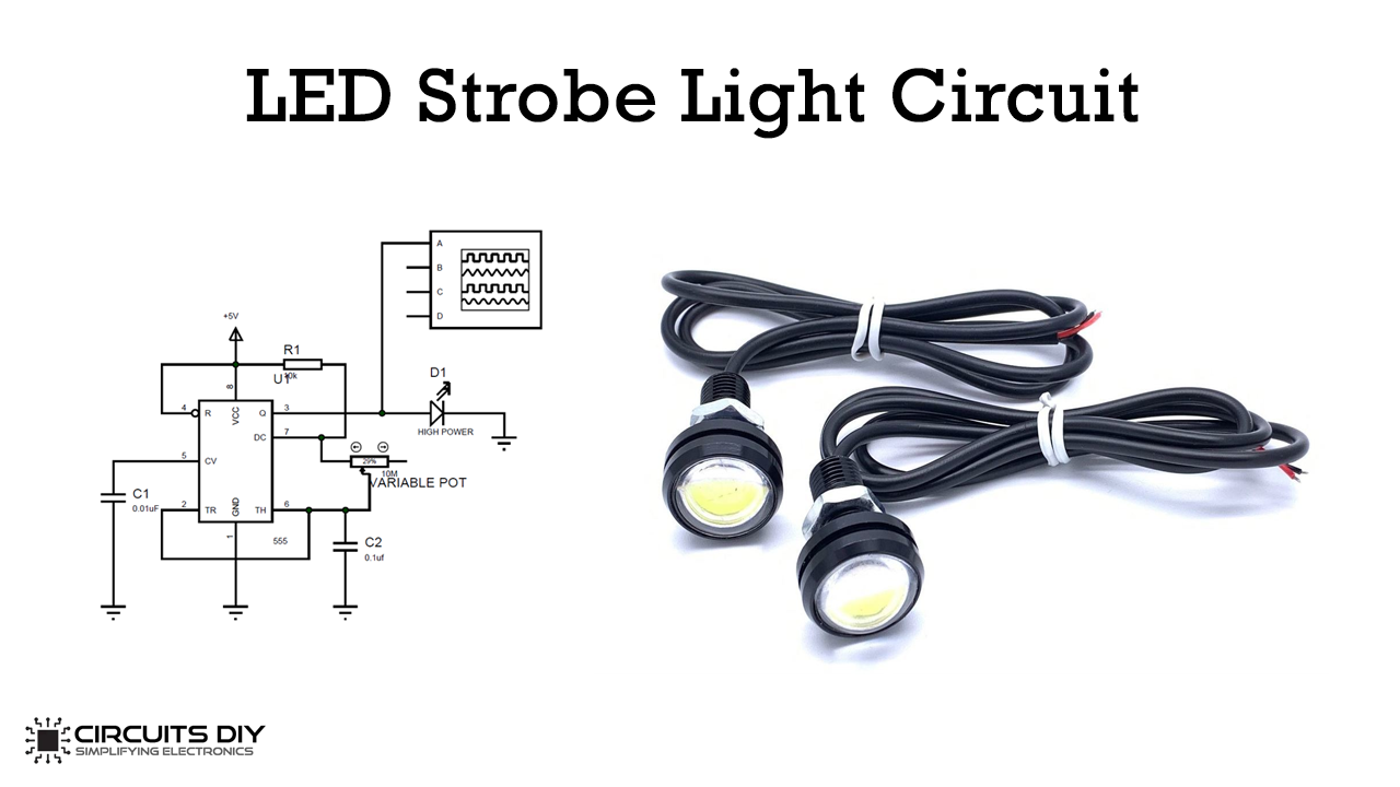
Strobe light produces regular flashes of light to create a strobe effect. In this project, we will make an LED Strobe circuit using the IC timer 555. We are designing this circuit using a 555 timer in the monostable mode for setting the delay between each flash.
Hardware Components
| S.no | Component | Value | Qty |
|---|---|---|---|
| 1. | Breadboard | – | 1 |
| 2. | Connecting Wires | – | 1 |
| 3. | Battery | 9v | 1 |
| 4. | IC | NE555 Timer | 1 |
| 5. | Variable Resistor | 1M ohm | 1 |
| 6. | Resistors | 10k | 1 |
| 7. | Ceramic Capacitor | 0.1uF,0.01uF | 1,1 |
| 8. | High Power LED | – | 1 |
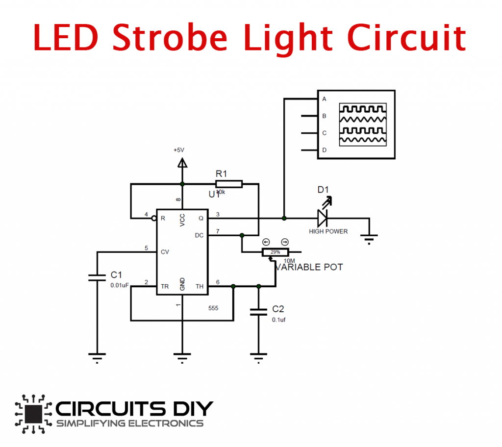
Connections
- Connect Pin 4 and 8 to VCC.
- Connect Pin 1 to GND.
- Add C1 and C2 Capacitors as shown in the circuit diagram.
- Add Variable Resistor between Pin 6 and 7.
- Connect the 0.1uF Capacitor between Pin 2 and GND.
- Connect the 0.01uF Capacitor between Pin 5 and GND
- Add 10k Resistor between VCC and Pin 7.
- Add High Power LED at Output Pin 3.
Strobe Light Circuit
The 555 timer IC will work as a stable multivibrator in this circuit. It will generate a continuous square pulse at the output. Wave will turn the LED On and off, and the duration depends on the duty cycle of the square wave. We can change the speed of the flashing of the LED by turning the knob of the potentiometer. 1-watt white LED has two terminals: anode (+) and the cathode (-). If you want to run this circuit regularly, then use an LED heat sink with the LED.
Applications
- We often use strobe lights for aircraft anti-collision lighting, on the aircraft themselves, and also on tall buildings.
- We use these lights in nightclubs and homes for entertainment or to produce special effects.