In this tutorial, we are going to make a “Pulse Width Modulation Circuit”.
A pulse width modulation signal consists of electronic pulses that are used to mimic a changing analog voltage, it is a technique that is used to precisely control analog devices with a digital signal. As most microcontrollers are unable to generate varying analog voltage. So, pulse width modulation is used to simulate varying analog voltage using a digital microcontroller or timer. We need a PWM signal because it has a lot of advantages and does the same work that is reducing the average power of transmitting an electrical signal by separating the signal into discrete samples. Here we design a simple and useful pulse width modulation circuit with timer IC 555. This circuit produces a continuous PWM signal without any input and by the variable resistor, the output frequency range can vary.

Hardware Components
The following components are required to make Pulse Width Modulation Circuit
| S.no | Component | Value | Qty |
|---|---|---|---|
| 1. | IC | NE555 Timer | 1 |
| 2. | Resistor | 10KΩ, 220Ω | 2,1 |
| 3. | Variable Resistor | 100KΩ | 1 |
| 4. | Ceramic Capacitor | 47nF, 10nF | 1,1 |
| 5. | Diode | 1N4007 | 2 |
| 6. | LED | – | 1 |
| 7. | Connecting Wires | – | – |
| 8. | Battery | 9V | 1 |
NE555 Pinout

For a detailed description of pinout, dimension features, and specifications download the datasheet of 555 Timer
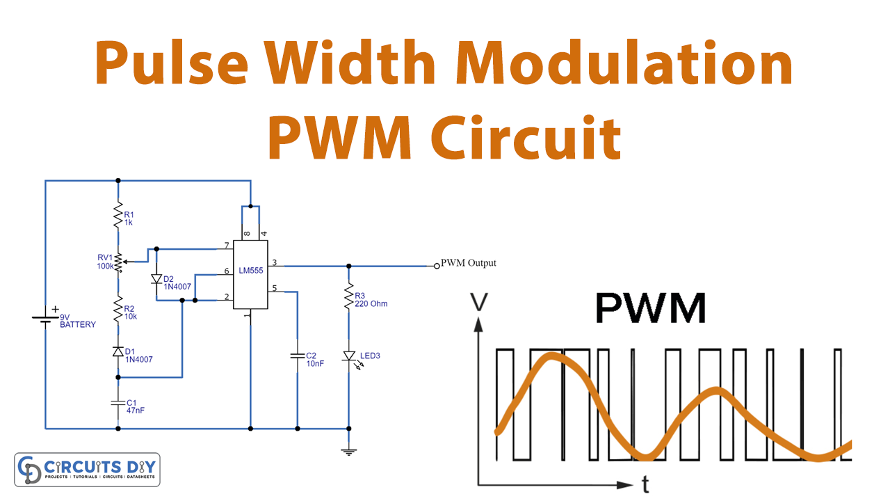
Pulse Width Modulation Circuit
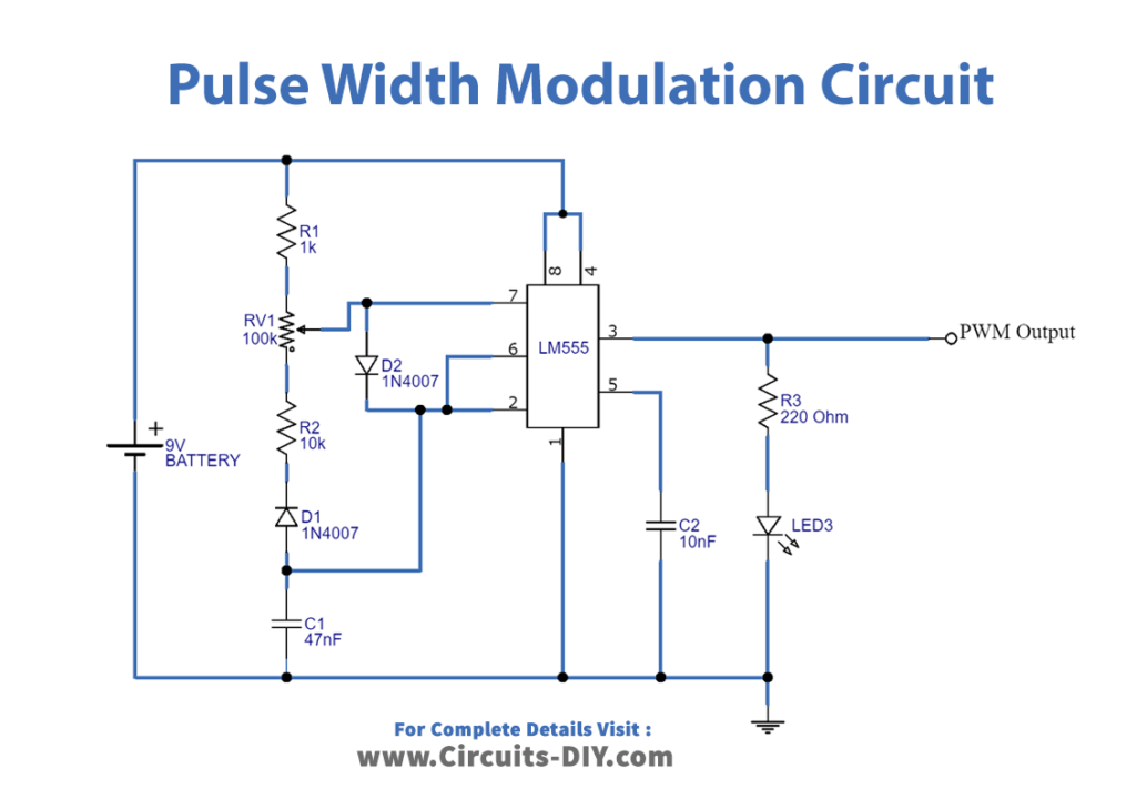
Working Explanation
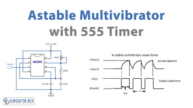
This circuit is designed to deliver PWM signals at the output at different levels of the duty cycle. Here we used IC 555 which is configured in astable multivibrator mode and output PWM was obtained for a continuous square pulse. The width of the Pulse is dependent on the amplitude of the input signal, the pulse duty cycle increases to the maximum level when the amplitude reaches the highest value and when the input signal amplitude reaches the lowest point the pulse width decreases to a minimum level. We can change the pulse width modulation output frequency by varying the timer element RV1. Here the LED indicates the duty cycle of output PWM with fading effect.
The percentage of time in which the PWM signal remains HIGH is called the duty cycle. If the signal is always ON it is in 100% duty cycle and if it is always OFF it is 0% duty cycle. Mostly a PWM signal stays on for a particular time and then stays off for the rest of the period, making this PWM signal special and more useful is that we can set how long it should stay on by controlling the duty cycle of the PWM signal. The formula to calculate the duty cycle is shown below.
Duty Cycle = Turn ON time / (Turn ON time + Turn OFF time)
How fast a PWM completes one period depends on the frequency of a PWM signal. One period is the complete ON and OFF time of a PWM signal. The formulae to calculate the Frequency are given below.
Frequency = 1 / Time Period
Time Period = ON Time + OFF Time
Applications
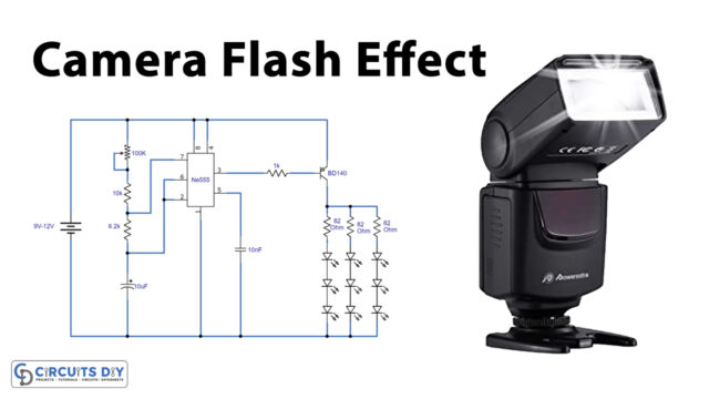
This circuit can be used in different PWM required places like voltage regulation, telecommunication, LED driver, servo motor driver, microcontrollers and integrated circuits, etc..,