Multivibrators are non-sinusoidal oscillators which are usually two-stage amplifiers with positive feedback. These circuits are made up of both active and passive components. Active components include elements such as BJTs, FETs, Vacuum Tubes, Op-Amps, and 555 timers ICs. Passive components include elements like resistors and capacitors.
Multivibrators can be of three types viz., astable multivibrators, monostable multivibrators, and bistable multivibrators. Astable multivibrators are the multivibrators that have no stable state i.e. the multivibrators in which the output continuously oscillates between two permissible states (the states present here are unstable i.e., quasi-stable. This means output swings between 0 and 1 and neither 0 nor 1 is the stable state). As a result, they produce square-wave at their output and are regarded to be free-running in nature. Further, these multivibrators do not require any kind of external triggering, except the DC supply, due to which they fall under the category of relaxation oscillators. Here we design a simple astable multivibrator by using IC555.
Hardware Required
| S.no | Component | Value | Qty |
|---|---|---|---|
| 1. | IC | NE555 Timer | 1 |
| 2. | Capacitor | 0.01uF,10 uF | 1,1 |
| 3. | Resistor | 330Ω | 1 |
| 4. | Variable Resistor | 100KΩ | 1 |
| 5. | Connecting Wires | – | – |
| 6. | Battery | 9V | 1 |
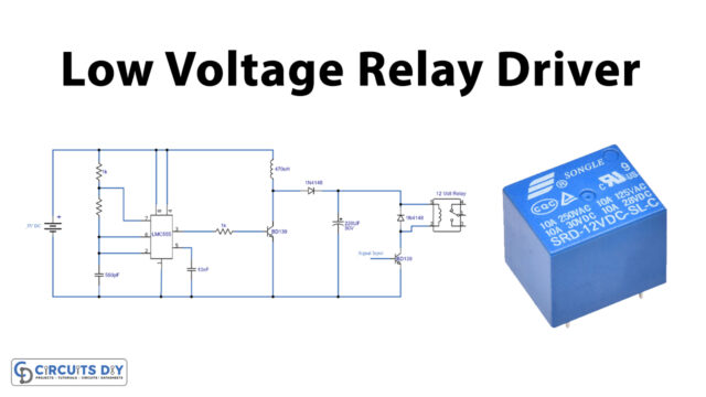
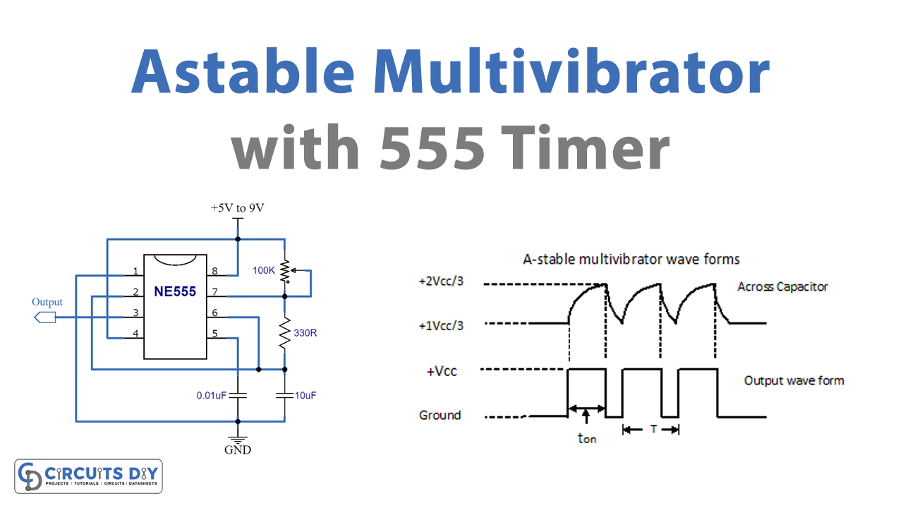
Circuit Diagram

Working Explanation
This circuit is actually a kind of relaxation oscillator where C1 is first allowed to charge to 2/3rd of the supply voltage via resistors R1 and R2, and then it is discharged by means of R2 to 1/3rd of the supply voltage. The working frequency can determine through the values selected for resistors R1, R2, and the capacitor C1, which may be calculated using the formula:
Frequency = 1.44/(R1 + 2R2)C1
The reason for incorporating the R1 value twice the value of R2 (instead of simply using both values identically) is that R2 is used during both the charge and discharge paths of C1 and so it has two times more effective than R1. The operating frequency could be altered by modifying the value of the C1 capacitor. Altering the value of C1 would produce an inversely proportional variation in frequency (for example if you double the C1 value will cause the frequency output to be halved and vice versa). Likewise, the operating frequency could be modified by changing the value of the timing resistance which would again result in an inversely proportional result for the frequency of the astable circuit.
Applications
Astable multivibrators are used in the applications like pulse position modulation, frequency modulation, etc. as they are simple, reliable, and easy to construct.