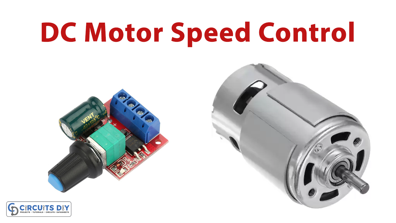
In this tutorial, we are going to make a “DC Motor Speed Control PWM circuit”.
A DC motor is an electro-mechanical device that converts direct current into mechanical energy using the rotation of a shaft. It works on the principle of Lorentz force by which the current-carrying conductor in a magnetic field experiences a force hence the conductor moves in the direction of force called Lorentz force. The DC Motor is used in many applications, and some applications require speed control of the DC motor sometimes it requires rotation direction control. Like if you are planning on assembling a robot, you will eventually need a DC motor controlling circuit. Now one of the easiest and most inexpensive ways to control DC motors is to use L293D Motor Driver IC. It can control both the speed and spinning direction of two DC motors.
Here we design a simple DC motor speed control PWM circuit by using IC 555 and motor driver IC L293D. Controlling the speed of the dc motor can be done in different ways like using a potentiometer and also by a controlled current to the armature. Apart from these techniques, to have complete control over the DC motor, we have to control its speed and rotation direction. This can be achieved by combining these two techniques.
- PWM – For controlling speed
- H-Bridge – For controlling rotation direction
PWM Signal
Pulse width modulation is an effective way to implement motor speed control. Pulse width modulation is a digital technique for coding digital data into a pulsating signal which looks like a square wave. The speed of a DC motor can be controlled by varying its input voltage. A common technique for doing this is to use PWM (Pulse Width Modulation). When we apply DC supply to the motor it starts to rotate the shaft but we cannot control its RPM (Revolutions per minute), but when we apply PWM signal as a supply to the DC motor depends on the PWM duty cycle we can control DC motors RPM. PWM is a technique where the average value of the input voltage is adjusted by sending a series of ON-OFF pulses.
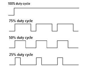
As the average voltage is proportional to the width of the pulses known as the duty cycle (depends on the ON time duration) and pulse counts motor speed (RPM) get varies with it. Hence higher the duty cycle, the greater the average voltage being applied to the dc motor (High Speed), and the lower the duty cycle, the less the average voltage being applied to the dc motor (Low Speed).
The below image illustrates the PWM technique with various duty cycles and average voltages.
H-Bridge Operation
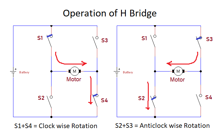
The DC motor’s spinning direction can be controlled by changing the polarity of its input voltage. A common technique for doing this is to use an H-Bridge. An H-Bridge circuit contains four switches with the motor at the center forming an H-like arrangement. A real-world H-bridge will not have ON/OFF switches. Instead, there will be 4-transistors which are electronic switches doing the job of reversing the polarity of the motor supply voltage. Now the motor gets forward and the reverse direction supply depends on the switch open and close, due to this the rotation varies clockwise or counterclockwise. Here closing two particular switches at the same time reverses the polarity of the voltage applied to the motor. That causes a change in the spinning direction of the motor, this is how the H-Bridge motor drivers are works.
The below animation illustrates the H-Bridge circuit working.
Hardware Required
| S.no | Component | Value | Qty |
|---|---|---|---|
| 1. | DC Motor | 1000 RPM | 1 |
| 2. | IC | L293D | 1 |
| 3. | IC | NE555 Timer | 1 |
| 4. | Variable Resistor | 100K | 1 |
| 5. | Resistor | 1K, 100Ω | 1, 2 |
| 6. | Ceramic Capacitor | 0.1μF | 1 |
| 7. | Diode | 1N4007 | 2 |
| 8. | Switch | – | 1 |
| 9. | Electrolytic Capacitor | 1μF | 1 |
| 10. | Battery | 9V | 1 |
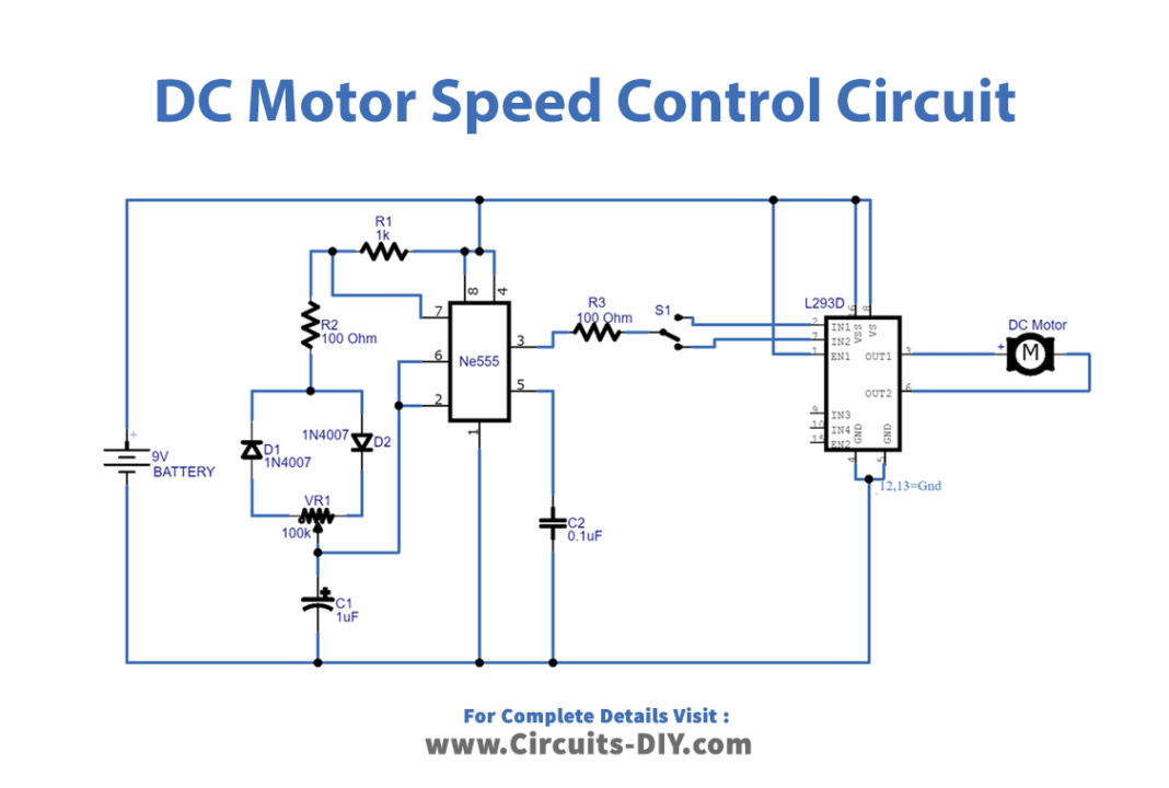
Circuit Diagram
L293D motor Driver

This integrated circuit (IC) L293D has 16 pins and is a 2-channel full H-Bridge motor driver, that is capable of driving two distinct DC motors. It’s the easiest way to go around building a whole H-Bridge driver from scratch. It comes in a DIP package which fits nicely on a typical breadboard. I like L293D is used to convert low power control signal to power enough signal to drive motors and to change the supply direction of load motor.
Working Explanation
In this circuit, IC 555 timer acts as a PWM generator and the H Bridge motor driver IC L293D takes responsibility to drive the motor depending on the PWM input signal, and the motor rotation direction can be changed by changing input pins.
Here when we powered the circuit, timer IC 555 generate a square pulse depending on the variable resistor value. Hence the output pulse width or duty cycle gets changed and the output from IC 555 is directly applied to the motor driver H-Bridge IC L293D through the toggle switch. Now by using the toggle switch we can change the input pin of L293D. The DC motor is connected between out 1 and out 2.
Applications
DC motors are widely used in industrial automation, toys, and robotics applications.