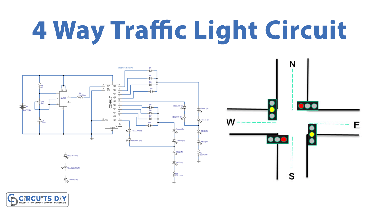
In this tutorial, we are going to make a “Four Way Traffic Light Circuit”.
Several decades back, when people used to travel on foot, there were, of course, no proper roads, and as vehicles got invented, the roads also got constructed. And, as technology increases, the construction of roads also gets more innovative. Today, there is not just a one or two-way route at one place, but also a 4-way road with 4-way traffic lights. As time passes, the population of the world is increasing, and not just the population, but also the automotive industry is growing. Thus, we need proper traffic management without that there would be chaos. Therefore, traffic signal lights are very Important to regulate vehicles and traffic on roads.
Here we design a simple four-way traffic light circuit with timer IC 555 and counter IC CD4017. We know each traffic signal light setup will have three colors and represent Red for STOP, Yellow for WAIT, and Green for GO, those signals are works based on time intervals. In this circuit timer, IC 555 works as an astable multivibrator to produce a pulse, this output pulse from IC 555 is fed into counter IC CD4017 clock input. It counts the pulse and changes the output line (Q) logic into HIGH or LOW. We can obtain traffic signal lights by connecting the proper color LED at this counter IC output.
Hardware Required
| S.no | Component | Value | Qty |
|---|---|---|---|
| 1. | Counter IC | CD4017 | 1 |
| 2. | IC | BE555 Timer | 1 |
| 3. | Diode | 1N4007 | 8 |
| 4. | LED Green | – | 4 |
| 5. | LED Yellow 4 | – | 4 |
| 6. | LED Red | – | 4 |
| 7. | Resistor | 1 KΩ, 220Ω | 1,3 |
| 8. | Variable Resistor | 20KΩ | 1 |
| 9. | Capacitor | 10μF | 1 |
| 10. | Connecting Wires | – | – |
| 11. | Battery | 9V | 1 |
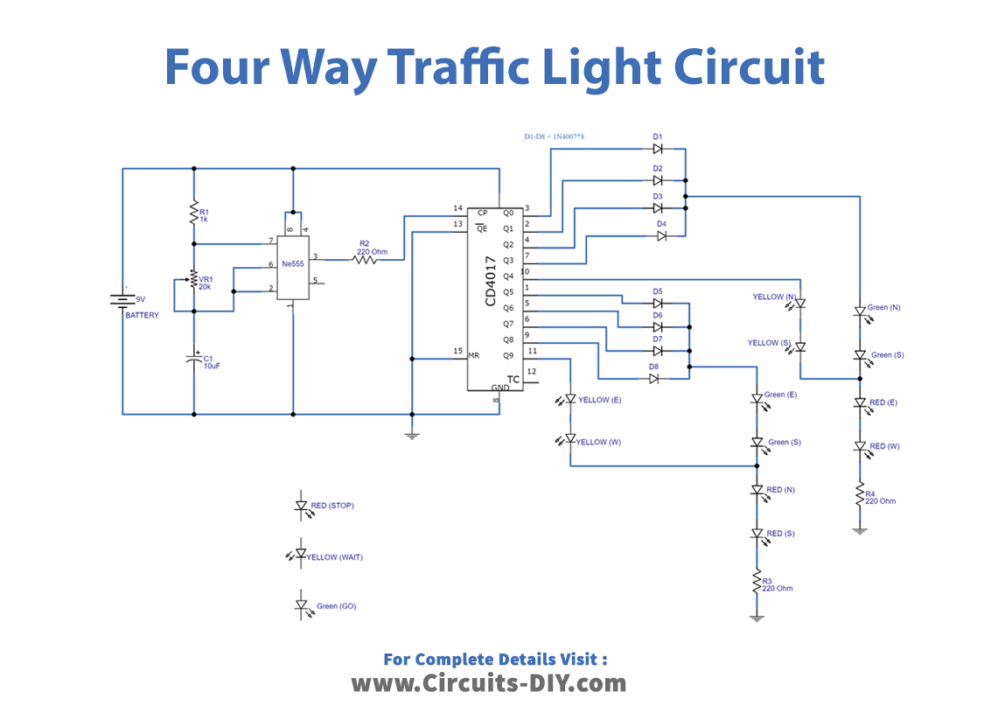
Circuit Diagram
Working Explanation
As we can see in the circuit, it has two stages first one is timing & counting the one is the Indication lights stage. Here timer IC 555 is placed with timing resistor R1, VR1, and timing capacitor C1. The output pulse sent at the output pin is based on the values of these elements.
Period= 0.693(R1+2VR1) C1
Frequency= 1.44/(R1+2VR1) C1
These pulses are deciding the timing interval of traffic light signals. And indication lights should be properly placed on four lanes. Here output pulse from the timer IC is fed into the counter IC CD4017 clock input through R2 Resistor. The counter IC has 10 outputs from Q0 to Q9, since we are making four-way traffic lights, therefore we have to consider all four lanes, which are east, west, north, and south. Here counter IC output Q0 to Q3 will drive a Green signal for North & South Lane, and a Red signal for East & West Lane. Output Q4 drives Yellow signal for North & South Lane. Output Q5 to Q8 will drive a Green signal for East & West Lane, Red signal for North & South Lane. Output Q9 drives a Yellow signal for East & West Lane. The ten-stage decade counter has a memory of ten, it can count up to ten pulses. So, for every peak at the clock, the counter admits it as an event and remembers it. The number of events that counter memorized outputted by the corresponding pin.
Applications
Used to control and regulate vehicles and traffic on heavy traffic roads, this work has been aimed at efficient means of controlling the traffic effectively for twenty-four hours.