Introduction
If you live in a hot region, you know the importance of cooling fans and their benefits. In cooling fans, cooler air is drawn into the case from outside, heated air is expelled from inside, and the air is moved over a heat sink to cool a specific component. Therefore, the cooling fan is also used in many other places. For example, in computers, kitchens, industries, etc. So, in this tutorial, we are going to make a “Cooling Fan speed control circuit”.
In the making of this circuit, we are using thermistors. The thermistor is basically a thermal resistor, resistance changes with the temperature change. Thus, the thermistor begins self-heating its components whenever the temperature changes.
Hardware Components
The following components are required to make Cooling Fan Speed Control Circuit
| S.no | Component | Value | Qty |
|---|---|---|---|
| 1. | NTC Thermistors | 470Ω | 4 |
| 2. | Cooling Fan | 1 | |
| 3. | Diode | 1N4007 | 1 |
| 4. | LED | – | 2 |
| 5. | Electrolytic Capacitor | 100uF | 1 |
| 6. | Resistor | 1KΩ, 390Ω, 10E, 1E | 2,1,4,1 |
| 7. | Battery | 9v | 1 |
| 8. | Connector | 2-Pin | 2 |
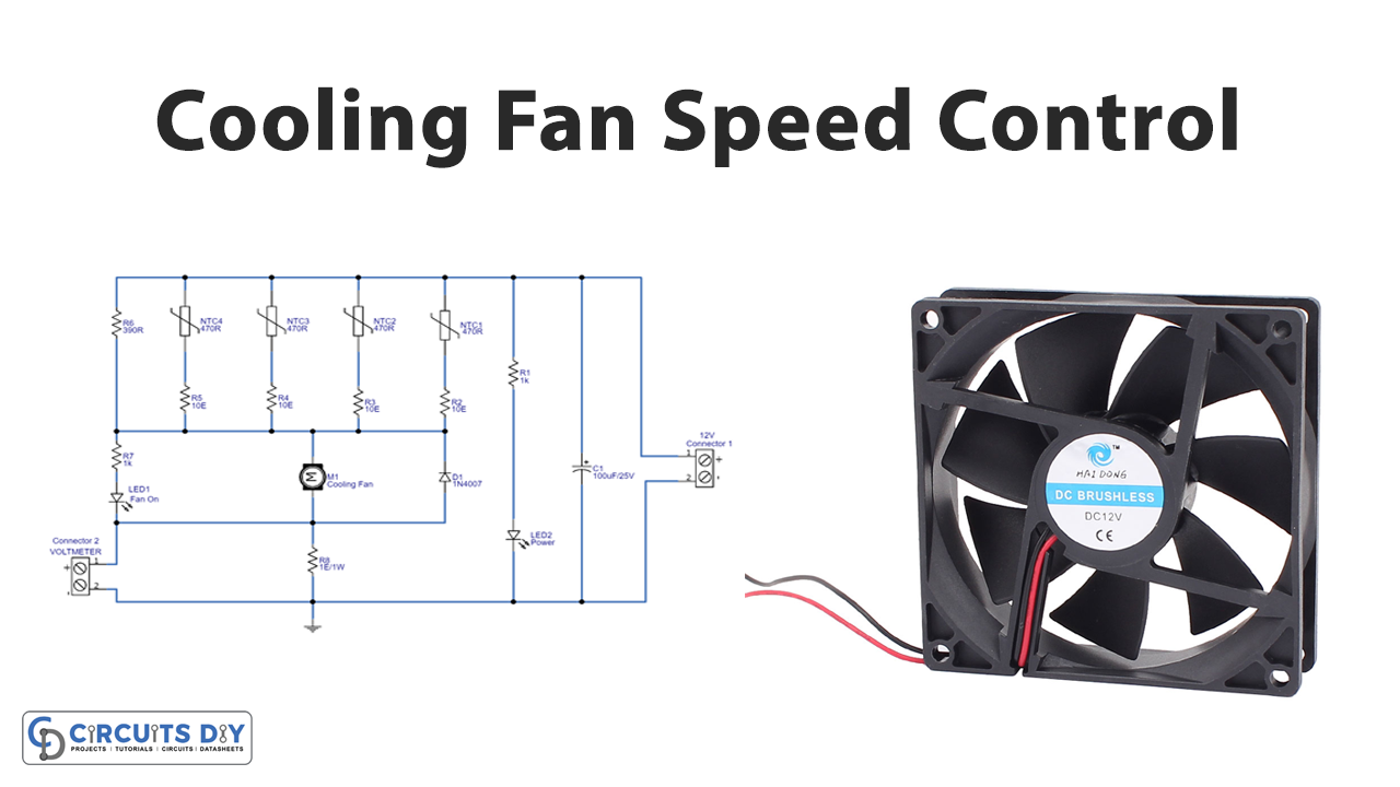
Cooling Fan Speed Control Circuit
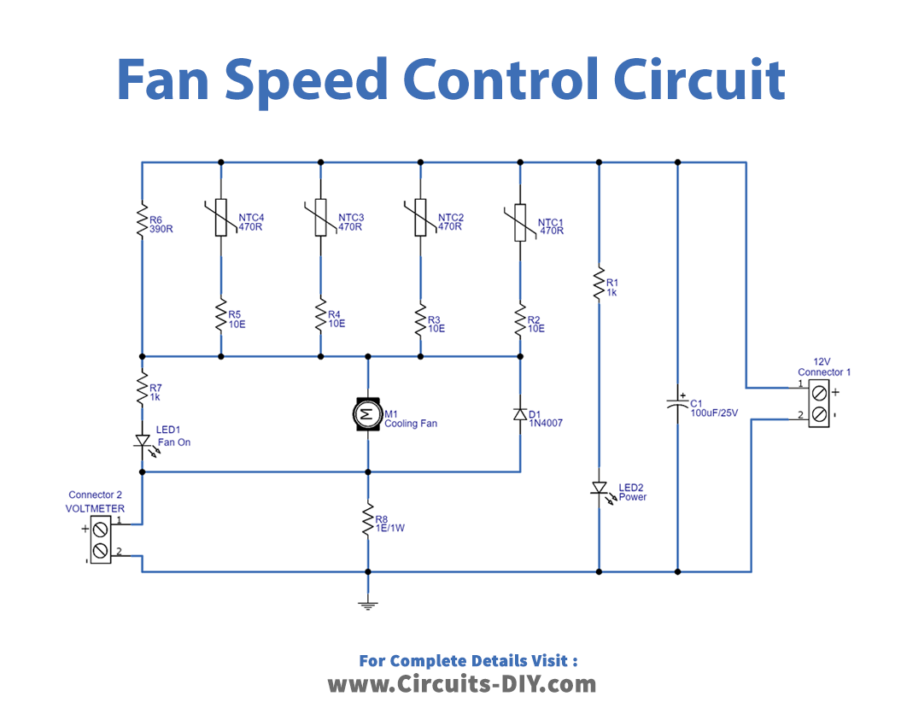
Working Explanation
This Cooling Fan speed control circuit has four thermistors of 470 ohms. When the temperature rises, this NTC thermistor provides low resistance to the power source, causing the fan speed to rise. In this way, the fan speed is automatically controlled by temperature. LED 1 is here in the circuit which turns ON when the fan turns ON.
Application and Uses
- The cooling fan is used in the ovens.
- In computers to cool down the CPU.
- In the industries. The fundamental function of s is to deliver cold air into the industrial surroundings while removing heated air.
- Cooling fans have great use in kitchens.