Introduction
If you appreciate the charm and simplicity of a classic doorbell but also crave something a little more unique, you’re in luck. The door buzzer circuit we’ll explore today is a delightful combination of old-school nostalgia and modern innovation. This unit is a true delight for those who want the best of both worlds – a nostalgic touch of Victorian-era door chimes and the thrill of modern innovation. The two-tone effect produced by this device will surely take you on a journey down memory lane while providing a unique and exciting experience with its state-of-the-art technology.
So, buckle up and get ready to dive into the fascinating world of door buzzers – it will be a wild ride!
Hardware Required
| S.no | Components | Value | Qty |
|---|---|---|---|
| 1 | IC | NE555, LM380N | 1, 1 |
| 2 | Transistor | 2N3904 | 1 |
| 3 | Resistor | 100K, 820K, 1M0, 47K, 100K, 10K, 68K | 1, 1, 1, 1, 1, 1, 1 |
| 4 | V. Resistor | 10K | 1 |
| 5 | Polar Capacitor | 1u0, 100u, | 1, 2 |
| 6 | Non Polar Capacitor | 100n, 6n8 | 1, 1 |
| 7 | Speaker | 8 – 40R | 1 |
Circuit Diagram
Circuit Explanation
Design and Oscillation:
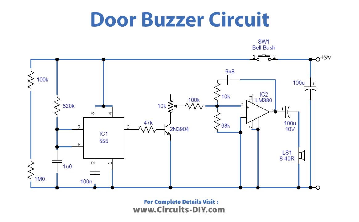
This door buzzer circuit is designed to oscillate using positive feedback between its output and non-inverting input, with the frequency of oscillation determined by the values of R6, R8, and C3. The desired values result in a working frequency of around 500Hz.
Audio Amplification and Loudspeaker:
The buzzer tone is produced using IC2, an LM380N audio power amplifier. The output from IC2 is delivered to a loudspeaker through DC blocking capacitor C4. and an output power of almost 1 watt RMS is achieved with an 8-ohm speaker.
Two-Tone Effect with 555 IC:
The two-tone effect is achieved by incorporating IC1 and its associated components. This is a 555 IC operating in monostable mode, producing a positive output pulse of just under one second in duration (determined by R3 and C1) when a negative trigger pulse is applied to pin 2.
Monostable Mode and Trigger Input:
This pulse is generated at power-on since C2 is initially uncharged. And will therefore pull pin 2 of IC1 to the negative supply potential. However, C2 quickly charges through R1. Causing the trigger input to become positive and preventing it from remaining negative at the end of the output pulse.
Frequency Adjustment with Q1 and R5:
During the output pulse, Q1 is biased into conduction via la, effectively connecting the series resistance of R5 and R7 in parallel with R8. This raises the operating oscillator frequency by an amount determined by R5. At the end of the pulse via IC1, the oscillator operates at its normal, lower frequency, producing the desired two-tone effect. We can adjust R5 to make two tones with a pleasing effect.
Power Consumption and Speaker Compatibility:
The current consumption of the door buzzer circuit ranges from around 100 mA with an 8-ohm speaker to about 40 mA with a 40-ohm speaker. While an 8-ohm speaker can deliver an output power of almost 1 watt RMS, a 40-ohm speaker will only provide about 200 mW RMS, which may still be sufficient for many applications.
Final Words
We hope you’ve enjoyed this deep dive into the world of door buzzers and that you’ve gained a greater appreciation for the clever engineering behind these simple devices.
The door buzzer circuit we’ve explored today is a testament to the power of positive feedback, and it’s remarkable how a few simple components can produce such an elegant and compelling sound. So experiment with your door buzzer circuit – who knows what new sounds you might discover!