Introduction
The 555 timer IC is one of the most useful Integrated circuits, utilized in various electronic projects. It’s a low-cost, widely used precision timing device that is used as a basic timer to create single pulses or large time delays, or as a relaxation, oscillator to generate a string of stabilized waveforms with duty cycles ranging from 50 to 100%. Since its internal circuitry includes a voltage divider network; made up of three 5K resistors, thus the name is 555. This IC may be used to produce precise time delays and oscillations. So, here in this article, we will discuss the Top 10 Easy Electronics Projects using NE555 Timer IC for Beginners.
(1) The Servo Controller
Hardware Required
| S.no | Component | Value | Qty |
|---|---|---|---|
| 1. | IC | NE555 Timer | 1 |
| 2. | Transistor | BC547 | 1 |
| 3. | SW forward, Reverse | – | 1,1 |
| 4. | Capacitor | 10μF, 100μF | 1,1 |
| 5. | Resister | 10KΩ, 36KΩ, 68KΩ 220Ω | 1,1,1,1 |
| 6. | Battery | 9V | 1 |
| 7. | 3-Pin, 2-Pin Connector | – | 1,1 |
Circuit Diagram
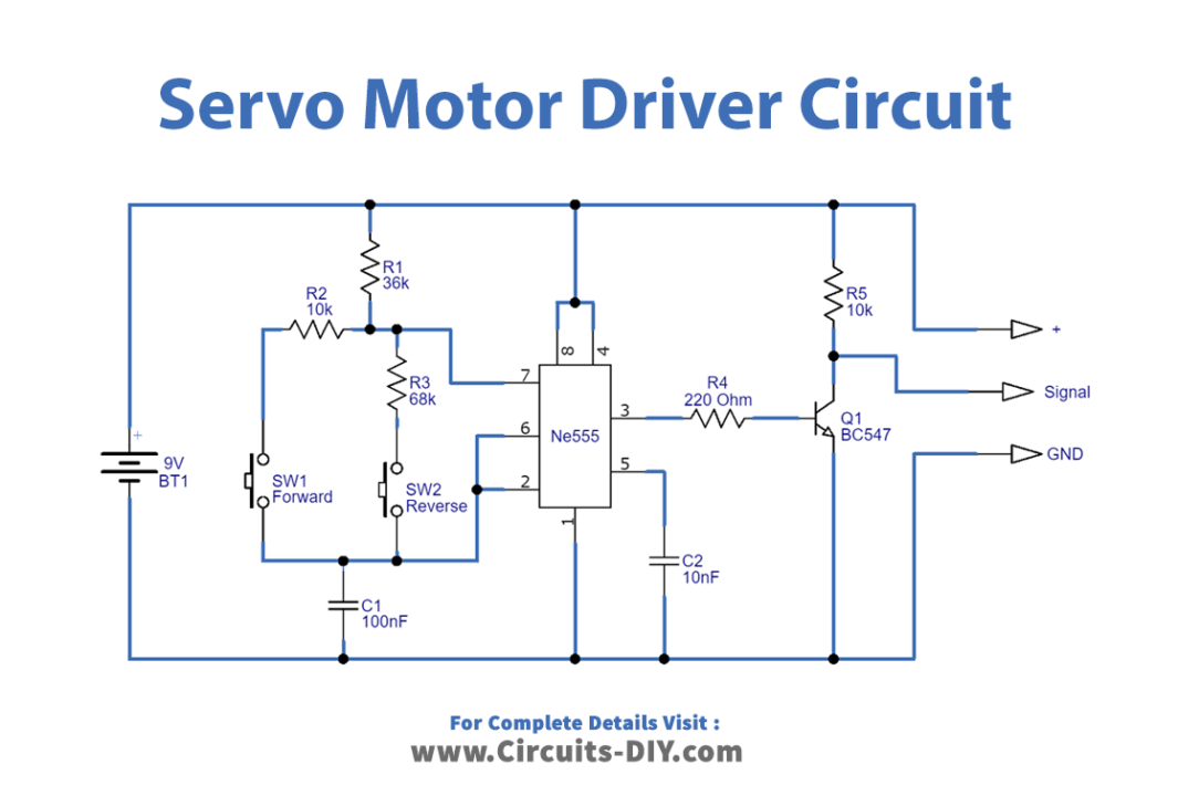
Working Explanation
In this Servo Motor Driver Circuit, we use IC 555 as an astable multivibrator and it generates the pulses at the output with two diverse duration. The pulse time of the output of the 555 timer IC depends on the timing resistor and Capacitor wired into the circuit.
When the switch SW1 is closed, the 555 clock IC generates a long-duration pulse, and the servo rotates in the clockwise direction And, when the switch SW2 gets closed, the 555 clock IC produces a short-duration high pulse and the servomotor rotates antilock wise. Thus, this is how the circuit works.
(2) LED Flashing Controller
Hardware Required
| Sr | Components | Qty |
|---|---|---|
| 1 | IC 555 Timer | 1 |
| 2 | LED Red, Green | 1,1 |
| 3 | Capacitor 1uF/ 16v | 1 |
| 4 | Resister 330Ω, 1KΩ, 100KΩ | 1,1 |
| 5 | Battery 9V | 1 |
| 6 | 2-Pin Connector | 1 |
Circuit Diagram
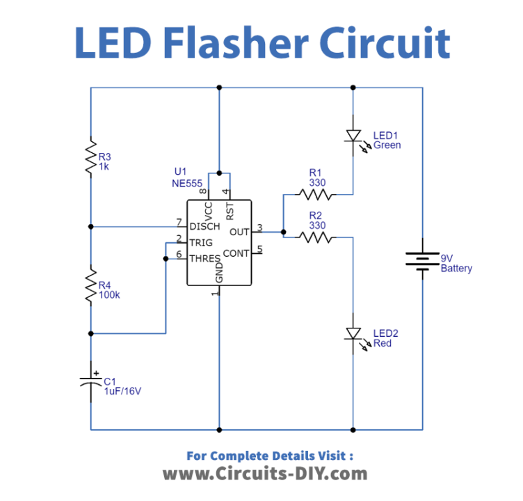
Working Explanation
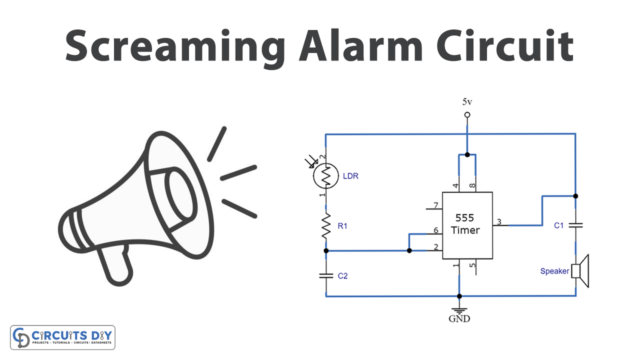
When light falls on the exterior side of the Light Dependent Resistor, the circuit flashes and makes a sound. The 555 timer IC, which is wired into the circuit as an astable multivibrator, is an important aspect of the circuit. As a darkness sensor, an LDR is employed. The circuit is controlled by a 10k variable resistor, which stimulates the alarm at the required amount of darkness. A speaker with an impedance of 8 ohms is connected to a capacitor with a capacitance of 4.7 microfarads and generates sound as an output. The frequency of the sound can be modified by changing the value of a 0.05 microfarad capacitor. The circuit works with a DC voltage range of 9 to 12 volts.
(3) Clap ON/OFF Switch
Hardware Required
| Sr | Components | Qty |
|---|---|---|
| 1 | IC 555 | 1 |
| 2 | Condenser Mic | 4 |
| 3 | IC 7474 | 1 |
| 4 | Relay 9V | 4 |
| 5 | Transistor BC547 NPN | 2 |
| 6 | Diode 1N4007 | 1 |
| 7 | Capacitor 10μF/16V, 0.01μF | 1,1 |
| 8 | Resistor 33KΩ, 1KΩ, 100KΩ | 1,1,1 |
| 9 | 9V Battery | 1 |
| 10 | 2-Pin Connector | 1 |
Circuit Diagram
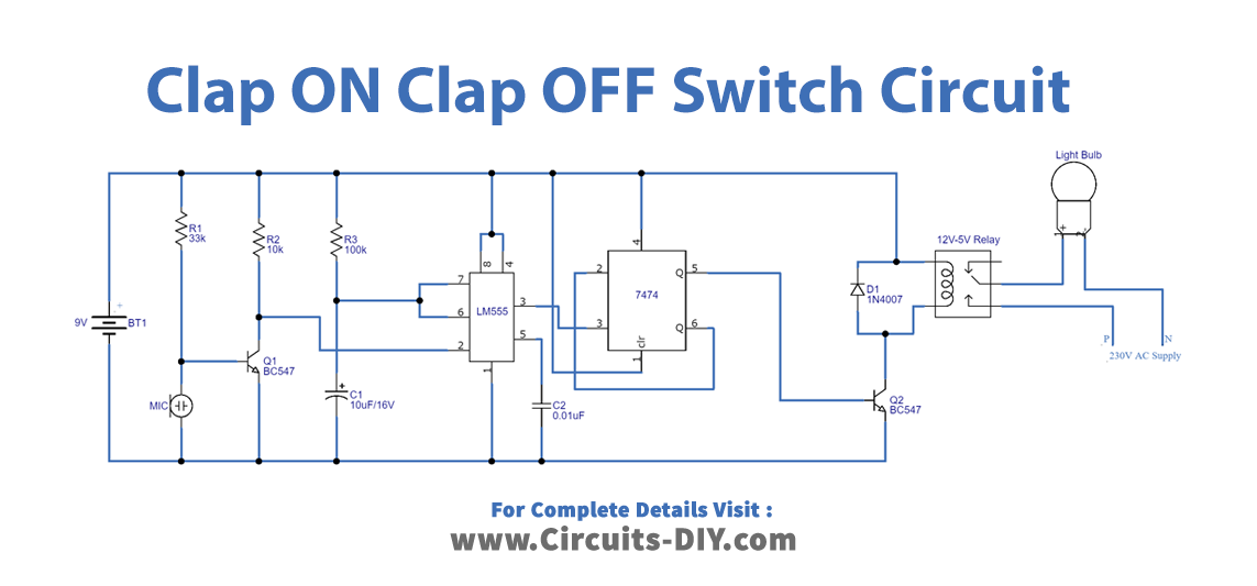
Working Explanation
This Clap ON Clap OFF Switch consists of two stages. The first one is the detecting stage having a Condenser microphone and 555 timer IC which is configured as a monostable multivibrator The output from the microphone is given to the triggered input pin of the timer IC. In the second stage, the output from the timer IC is given to the clock input of the D flip flop. In other words, you can say that the timer Ic s providing a clock to flip-flop IC. The D flip flop recognizes a positive edge of the pulse and changes its state accordingly. Output from the flip flop is given at the base of the transistor which drives the relay.
When you clap near the condenser microphone, it generates some spike which will trigger the timer IC, and hence Ic generates a mono pulse which is taken by flip flop IC. The flip flop detects the positive edge in the pulse and changes its state to ON or OFF depending on the current state.
(4) The Brightness Sensor
Hardware Required
| Sr | Components | Qty |
|---|---|---|
| 1 | LDR | 1 |
| 4 | Capacitor (0.05uf, 4.7uf) | 1 |
| 5 | Potentiometer 10KΩ | 1 |
| 6 | speaker | 1 |
| 7 | Resistor 1k, 1.2k, 47k | 1, 1, 1 |
| 8 | 555 Timer IC | 1 |
| 9 | 9V battery | 1 |
Circuit Diagram
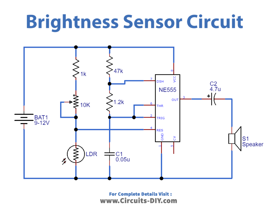
Working Explanation
When light falls on the exterior side of the Light Dependent Resistor, the circuit of light-actuated alarm employing 555 timers IC makes a sound (LDR). The 555 timer IC, which is attached to the circuit as an astable multivibrator, is an important aspect of the circuit. As a darkness sensor, an LDR is employed. The circuit is controlled by a 10k variable resistor, which stimulates the alarm at the required amount of darkness. A speaker with an impedance of 8 ohms is connected to a capacitor with a capacitance of 4.7 microfarads and generates sound as an output. The frequency of the sound may be modified by changing the value of a 0.05 microfarad capacitor. The circuit works with a DC voltage range of 9 to 12 volts.
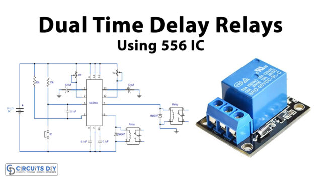
(5) Timer Alarm Circuit
Hardware Required
| Sr | Components | Qty |
|---|---|---|
| 1 | IC 555 | 1 |
| 2 | Buzzer | 1 |
| 3 | Switch | 6 |
| 4 | Electrolysis Capacitor 470uF | 1 |
| 5 | Capacitor 0.1uF | 1 |
| 6 | Resistor 100Ω, 20KΩ, 500KΩ, 1MΩ, 2.2MΩ, 1.5MΩ | 1,1,1,1,1,1 |
| 7 | Switch | 1 |
| 8 | Lithium-Ion Battery | 1 |
Circuit Diagram
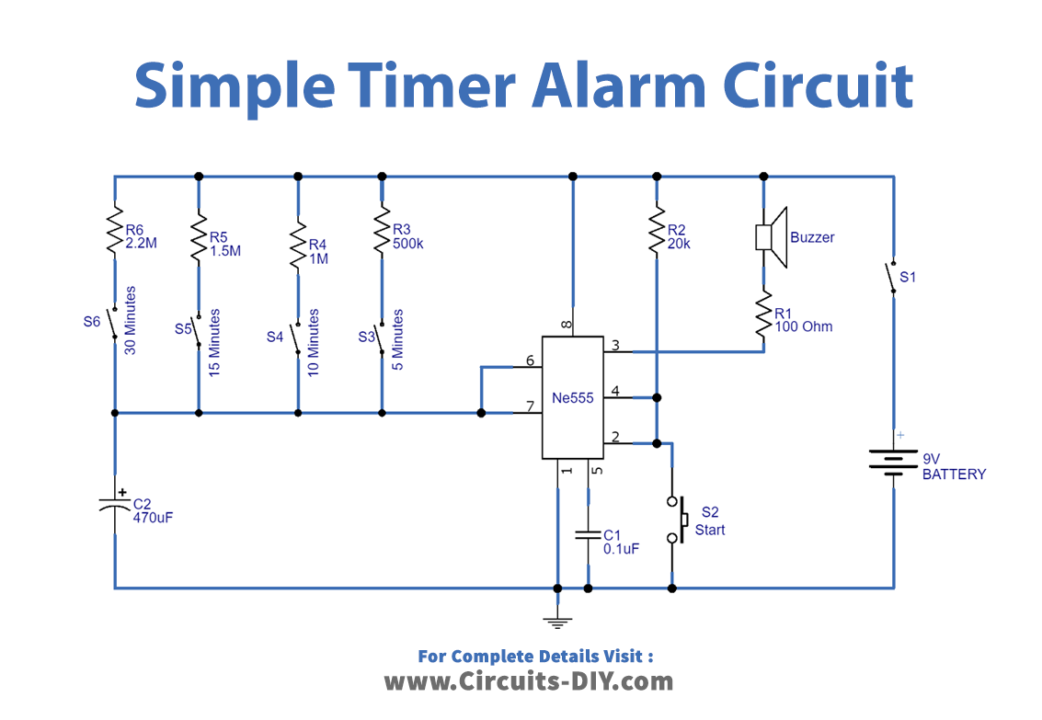
Working Explanation
In this Simple Timer Alarm Circuit, timer IC 555 is the major circuit component with few other components which are easily available, A 9V battery is used as the supply, and you can also create your own power supply by using a step-down transformer and Bridge Rectifier circuit. We connected the buzzer at the output pin of the timer IC. The start button is connected at pin 2 and through R2 Resistor. The circuit has a different range of Resistors for various timing ranges. You can turn ON this circuit by closing Switch S1. Choose the timer range by closing the switches S3, S4, S5, or S6 and then press the start switch s2 and then wait. On the output side, the buzzer will give the sound depending on the timing range.
(6) The Dark Sensor
Hardware Required
| Sr | Components | Qty |
|---|---|---|
| 1 | LDR (Any size) | 1 |
| 2 | IC 555 Timer | 1 |
| 3 | piezo buzzer | 1 |
| 4 | Potentiometer 1MΩ | 1 |
| 5 | Capacitor 1uF/25V, 0.01uF | 1,1 |
| 6 | Resistor 2.2KΩ, 10KΩ | 1,1 |
| 7 | Connecting wires | – |
| 8 | Battery 9V | 1 |
| 9 | 2-Pin Connector | 1 |
Circuit Diagram
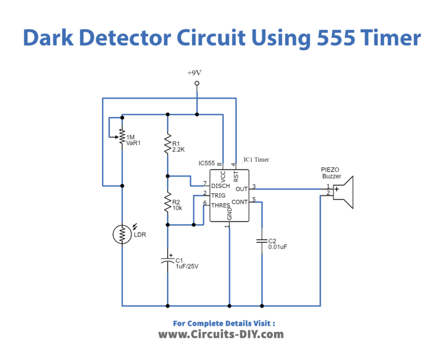
Working Explanation
The 555 timer IC serves as an astable multivibrator circuit in this Darkness detection circuit. The circuit has a variable resistor that allows us to adjust the sensitivity. There is no current flow across the circuit when a continuous light falls on the LDR. The LDR senses the darkness and lowers its resistance if something happens between the light and the LDR. The electricity then flows through the circuit. The buzzer beeps as a result.
(7) DC Speed Controller
Hardware Required
| Sr | Components | Qty |
|---|---|---|
| 1 | IC 555 Timer | 2 |
| 2 | Transistor IRF 540 | 1,1,1 |
| 3 | Motor | 1 |
| 4 | Diode 1N4007 | 1 |
| 5 | Potentiometer 100K | 1 |
| 6 | capacitor 1000uF, Ceramic Capacitor 0.47uF | 1,1 |
| 7 | Register 10K, 47K, 560 Ohm | 1,1,1 |
| 8 | Battery 12v | 1 |
Circuit Diagram
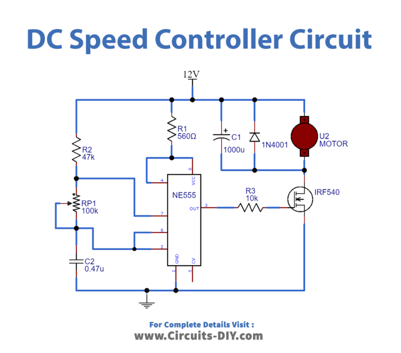
Working Explanation
In this DC motor speed control using IC 555, when we give an input supply of 12V to the circuit, the 555 timer IC generates the pulses at the output pin 3. The pulses depend on the potentiometer wired into the circuit. This output pulse from IC controls the MOSFET connected in the circuit as the output is given the base of the MOSFET which is then wired with the motor to control the speed. Hence, the speed can be controlled or varied by a potentiometer in the circuit.
(8) Touch ON OFF Switch
Hardware Required
| Sr | Components | Qty |
|---|---|---|
| 1 | Touch plate (refer to text) | 1 |
| 2 | IC 555 Timer | 1 |
| 3 | LED | 1 |
| 5 | Capacitor 10uF/25V, 0.01uF | 1,1 |
| 6 | Resistor 100KΩ, 470Ω | 1,1 |
| 7 | Connecting wires | – |
| 8 | Battery 6 | 1 |
| 9 | 2-Pin Connector | 1 |
Circuit Diagram
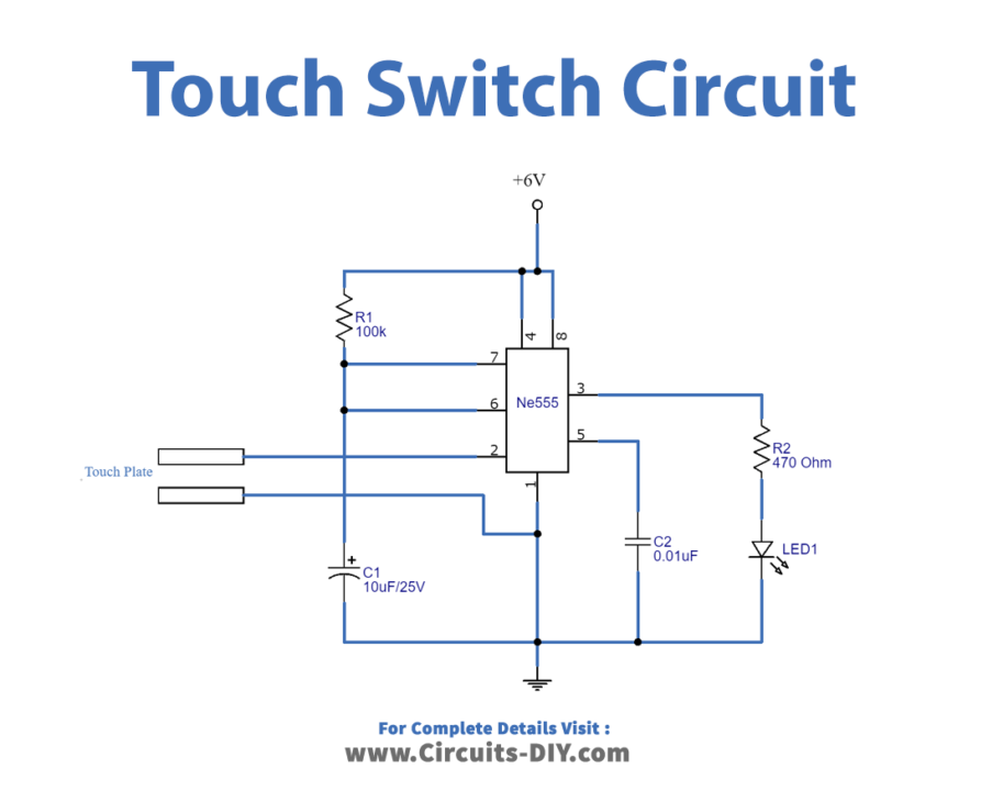
Working Explanation
The NE555 IC is used to create pulses in this circuit hence, works as a monostable multivibrator. Human contact is detected by a touch plate. When you place your finger on the touch plate, the signal is received by an IC’s trigger pin, which generates a mono pulse on the output side. Keep in mind that the pulse is determined by the timing capacitor c1 and the resistor R1. A LED is linked to the output side, which turns on when the pulse is received.
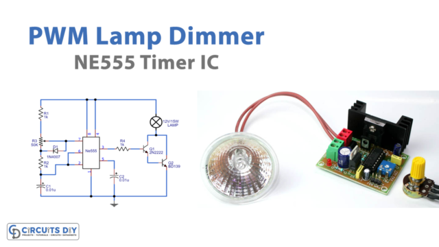
(9) LED Dimmer Circuit
Hardware Required
| Sr | Components | Qty |
|---|---|---|
| 1 | NE555 Timer IC | 1 |
| 2 | IRFZ44 | 1 |
| 3 | Powerful LED | 1 |
| 4 | Potentiometer (10-50k) | 1 |
| 5 | 1n4007 Diode | 2 |
| 6 | Resistor 1k | 2 |
| 7 | Ceramic Capacitor 100nF ,10nf | 1,1 |
| 8 |
Circuit Diagram

Working Explanation
The 555 timer acts as an astable multivibrator in this LED Dimmer Circuit, generating PWM pulses. Timing components such as resistors, potentiometers, and capacitors are included in the circuit. The potentiometer controls the duty cycle of the PWM signal. When the duty cycle is high, the light intensity is higher; when the duty cycle is low, the light intensity is lower. The diodes are utilized at the trigger pin to bypass the cycle of a wired potentiometer during IC charging in astable mode, as well as to control the constant frequency regardless of the duty cycle. MOSFETs are linked to the output of an IC to power the bright LED.
(10) LED Chaser Circuit
Hardware Required
| S.no | Component | Qty |
| 1 | CD4017 Decade Counter IC | 1 |
| 2 | PCB board for circuit | 1 |
| 3 | NE555 Timer IC | 1 |
| 4 | Potentiometer | 1 |
| 5 | power jack | 1 |
| 6 | Capacitors (1uF, 0.01uF) | 1, 1 |
| 7 | Resistors (10K, 680 ohms) | 1, 2 |
| 8 | 9V Battery | 1 |
| 9 | LEDs | 11 |
Circuit Diagram
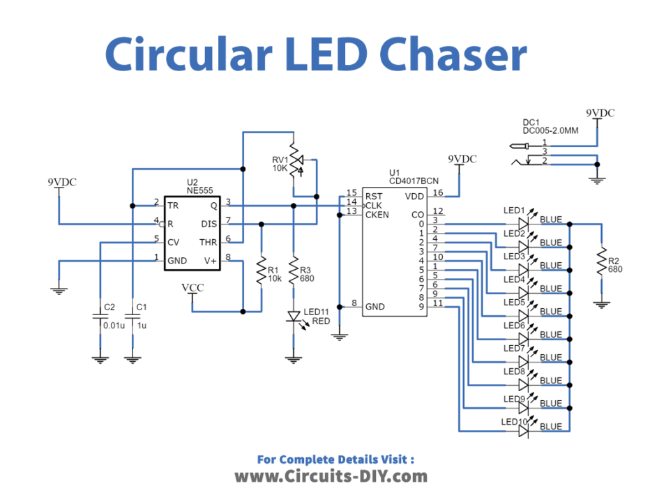
Working Explanation
In this Circuit using 555 and 4017, the clock input of the CD4017 decade counter IC is wired to the NE555 timer. The timer IC provides the decade counter’s CLK input with square wave input. Each pin on the CD4017 connects to an LED. By default, the ic’s output pin is high while it turned the remaining pins off. When the clock input pin of the 4017 IC detects a voltage rise from low to high, it turned the current output off and the next consecutive output gets turned on.
This output change, which appears to be the LEDs chasing each other, continues until it reached the last LED, at which point the output is reset to the first LED.