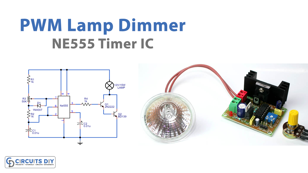
Introduction
Ever wondered how the dimming lights work? Ever marveled that how its light intensity goes higher and lower? In this project, we are going to explore an efficient PWM lamp dimmer using a 555 timer IC. The dimmer can also be made by the linear regulator but that would be only fifty percent efficient, while PWM dimmers can be ninety percent efficient. And because of this high-efficiency rate, it minimized the heat loss from the circuit
The lamp mirrors do not need any switches and the intensity of light is controlled by the potentiometer. Be aware while making this project because the lightning dimmers can only handle a specific amount of load. This PWM dimmer circuit has a 555 timer IC as the main component which is connected as an astable multivibrator.
Hardware Required
| S.no | Component | Value | Qty |
|---|---|---|---|
| 1. | NPN Power Transistor | BD139 | 1 |
| 2. | IC | NE555 Timer | 1 |
| 3. | Transistor | 2N2222 | 1 |
| 4. | Diode | 1N4007 | 1 |
| 5. | Potentiometer | 50K | 1 |
| 6. | Capacitor | 0.01uF | 2 |
| 7. | Resistor | 1K | 1 |
| 8. | Lamp | 12V/5W | 1 |
| 9. | Battery | 12V | 1 |
| 10 | Bread Board | – | 1 |
Circuit Diagram
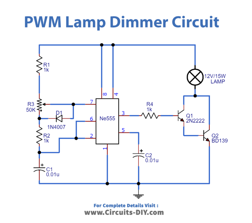
Working Explanation
NE 555 timer IC here operates at 2.8KHz and works as a stable multivibrator. Resistors, potentiometers, and capacitors are timing components in this circuit. The potentiometer adjusts the duty cycle of the output of the IC. The greater the duty cycle, the greater would be the light intensity, the lights get less intense on the low duty cycle
The diode is used to bypass the lower half cycle of the potentiometer during the charging of the IC in a stable mode and to maintain the constant frequency irrespective of the duty cycle. Transistors are used to set the Darlington stage for the lamp.
Application And Uses
- It can be used in headlight
- In rear light
- Ring lights can also be used in this circuit
- This circuitry can also be used for simple bedroom lamps