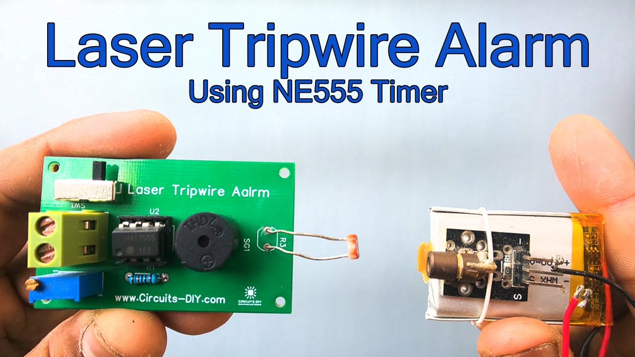
A laser tripwire security alarm is a simple security system that can detect the movement of any intruding person or object passing through the beam of a laser & triggers an alarm accordingly. The red line laser actually triggers a latching switch, that can be connected to any external load/security device such as a loudspeaker alarm, floodlight, or CCTV cameras.
Laser tripwire alarms have become a staple for home security systems & mandate their presence in every security detail for any place. So, in today’s tutorial, we will go over a step-by-step procedure on how to design a simple Laser Tripwire Security Alarm using an LDR & a NE555 timer IC.
Thank You NextPCB:
This project is successfully completed because of the help and support from NextPCB. NextPCB is one of the most experienced PCB manufacturers in Global and has specialized in the PCB and assembly industry for over 15 years. Not only could NextPCB provide the most innovative printed circuit boards and assembly technologies in the highest quality standards, but the fastest delivery turnaround was also as fast as 24 hours.
Guys if you have a PCB project, you can visit their website and get exciting discounts and coupons on the following:

Hardware Components
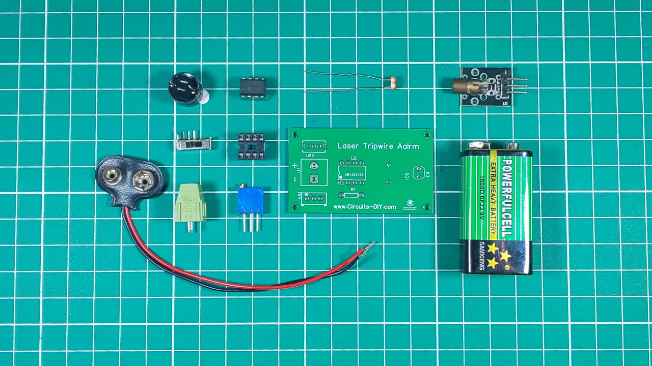
The following components are required to make Laser Tripwire Alarm Circuit
| S.no | Component | Value | Qty |
|---|---|---|---|
| 1. | Laser diode/pointer | 5V, 650nm, 5mW | 1 |
| 2. | IC | NE555 Timer | 1 |
| 3. | Laser Security Alarm PCB | PCB | 1 |
| 4. | LDR | 5mm | 1 |
| 5. | Buzzer | 5V | 1 |
| 6. | Latching Switch | SPDT | 1 |
| 7. | Resistor | 10K | 2 |
| 8. | Soldering Iron | 45W – 65W | 1 |
| 9. | Soldering Wire with flux | – | 1 |
| 10. | DC Battery | 9V | 1 |
| 11. | Heat Shrink Tubing | – | 0.5ft |
| 12. | Variable Resistor | 10K | 1 |
NE555 IC Pinout

For a detailed description of pinout, dimension features, and specifications download the datasheet of 555 Timer
Laser Tripwire Alarm Circuit
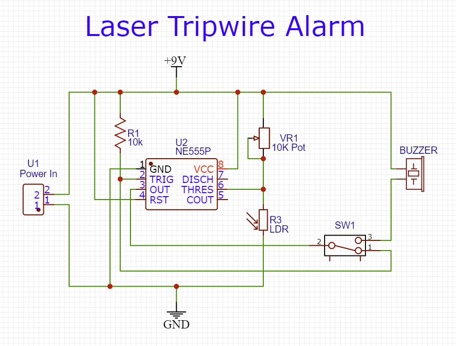
Working Explanation
This laser tripwire circuit triggers an alarm when the line of sight between the laser beam & the LDR is interrupted. The design of this circuit is based on a 555-timer IC. A photoresistor (LDR) is used to detect the laser light from the laser diode. The LDR & the 220Ohm resistor together form a voltage divider circuit.
When the laser beam is interrupted, the light intensity over the LDR decreases, increasing its resistance, this causes the voltage at pin 6 (Threshold) to rise above the reference threshold voltage. This triggers the output at pin 3 (Output) to go low & activate the Buzzer. When the line of sight between the laser pointer & the LDR is re-established its resistance decreases, causing the voltage divider output to fall well below the reference threshold voltage at pin 6 of the IC, disconnecting the output pin 3 from the latch switch which turns off the alarm.
Applications
- Laser security alarms are used in places such as residential, commercial, industrial, and military properties for protection against theft or property damage.
- Also used in high-risk/sensitive areas such as military bases, security vaults & supermax prisons.