In this tutorial, we are going to make a “Simple Broken Wire Detector”.
When a wire is shorted out or is broken inside a wall or over the insulator and you need to locate it then an electric circuit detector should help to find the wire. To identify the broken wire location, we design a system by using only transistors. It can easily detect the location of internal snapping without contact and physical disturbance. By using a simple broken wire detector, we can identify the presence of current flow, when it senses the breakage in the faulty wire it means there is no current flow than the buzzer and LED become off. Now the user knows the location of the fault, so the broken section of the wire can be replaced easily.

Hardware Component
The following components are required to make Broken Wire Detector Circuit
| S.no | Component | Value | Qty |
|---|---|---|---|
| 1. | Transistor | BC547 | 3 |
| 2. | Buzzer | 5V | 1 |
| 3. | LED | 1 | |
| 4. | Resistor | 100KΩ, 10KΩ, 100Ω | 1,1,1 |
| 5. | Switch | – | 1 |
| 6. | Connecting Wires | – | – |
| 7. | Battery | 9V | 1 |
BC547 Pinout

For a detailed description of pinout, dimension features, and specifications download the datasheet of BC547
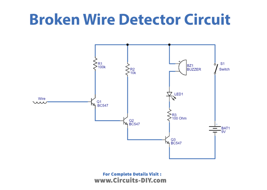
Broken Wire Detector Circuit
Working Explanation
As we know that normal wire can be used as an antenna to pick up electromagnetic force (EMF) from the current flowing wire. Take a short length wire as an antenna and connect it to the base terminal of the Q1 transistor, this Q1 transistor is biased through 100KΩ Resistor and the emitter terminal connected to the base of the Q2 transistor this is biased through 10KΩ Resistor then the emitter terminal of Q2 is connected to the base of Q3 transistor, Buzzer and LED Connected at the collector terminal of Q3 through 100Ω Resistor, the whole circuit is biased with 9V battery. Here three-stage transistors operate as amplifiers and strengthen the detected signal from the current flowing wire. This strengthened signal makes the buzzer produce a beep sound and the LED blink. When the antenna wire is placed near the current flowing wire it will pick up the EMF signal and after amplification by three transistors, a buzzer, and an LED makes an indication. When the wire is broken then there will be no current flow in the wire and no EMF then Buzzer and LED stay in turn OFF position, hence there is no indication from the buzzer and LED.
Applications
Can be used in electrical troubleshooting and repairing a damaged electric circuit.