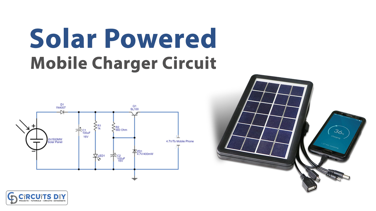
As we know iPods, smart watches, etc. have become an important part of our life. And they all need to charge after regular usage, which especially becomes a major concern when you are in a place where electricity is not available. One of the solutions to these kinds of problems is to depend on renewable energy sources. There are different types of renewable energy sources like wind, tidal, solar, etc. In today’s project, we are going to use solar energy to charge our mobiles. To convert solar energy into electricity, we will need solar panels. Here we design a solar mobile phone charger circuit to charge our mobile phone as well as to protect the battery from overcharging. Before trying this circuit take extra care in battery polarity and current rating, if anything goes wrong the battery might explode.
Hardware Required
| S.no | Component | Value | Qty |
|---|---|---|---|
| 1. | Solar Panel | 6V/500mW | 1 |
| 2. | Diode | 1N4007 | 1 |
| 3. | Transistor | SL100 | 1 |
| 4. | Resistor | 1KΩ,560Ω | 1,1 |
| 5. | Capacitor | 100uF/16V | 2 |
| 6. | Zener Diode | 4.7V/400mW | 1 |
| 7. | Connecting Wires | – | – |
| 8. | LED | – | 1 |
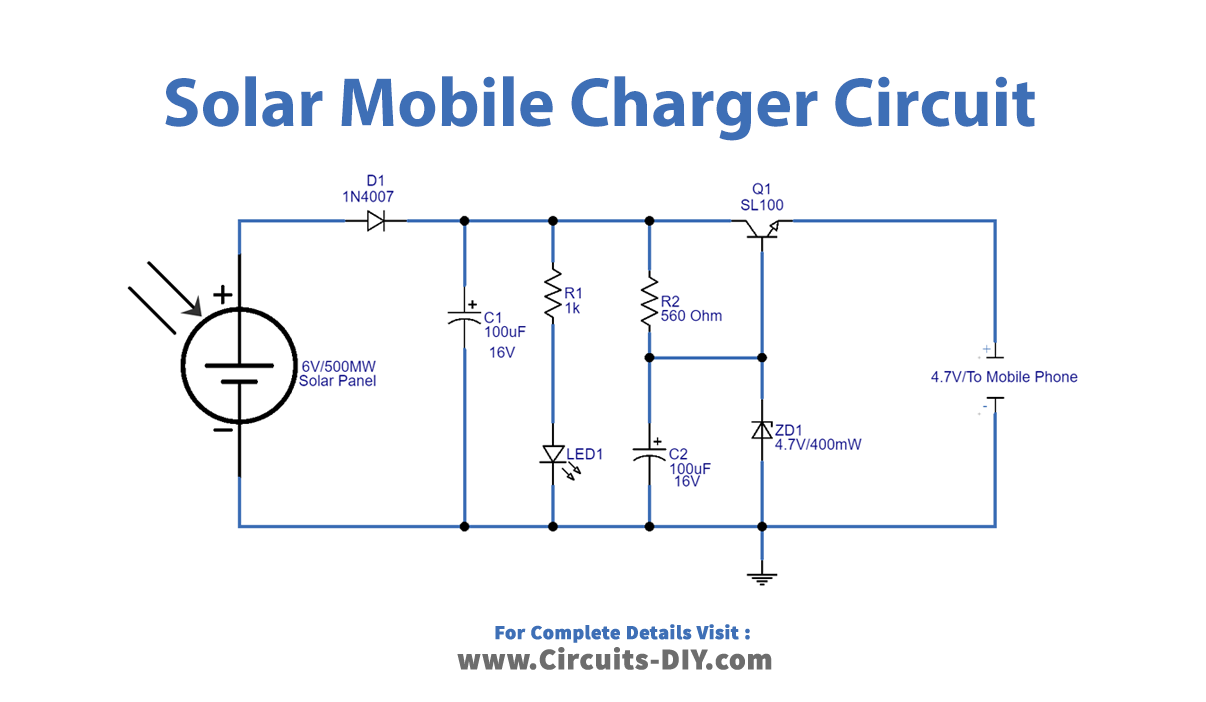
Circuit Diagram
Circuit Construction and Working
In this circuit, we have utilized a 6V/500 mW solar panel, and then to avoid reverse polarity single PN junction diode 1N4007 connected towards the positive line of the solar panel. To provide the status of supply output from solar panel green LED connected across the solar panel supply line after the C1 capacitor. Here you can remove R2 and LED if you don’t need a light indicator. Further SL100 transistor with 4.7V/400mW is connected and the Zener diode provides a regulated supply from solar voltage. It is connected to the base of the SL100 transistor with reverse-biased polarity. Now according to your need choose the Zener diode specification.
When you expose the solar panel to sunlight, that solar energy will be converted as a voltage by the photovoltaic device (solar panel cell), then the green LED glows. Here the intensity of this LED varies depending on the voltage produced by the solar panel. The Zener diode reduces and regulates voltage and the SL100 transistor drives output voltage.
Test Points
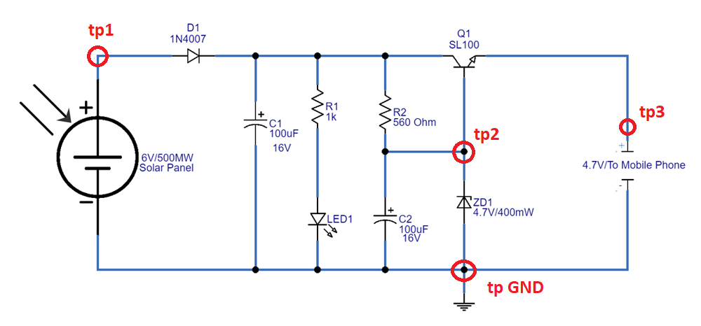
- tp GND – test point common ground
- tp 1 – To check solar panel voltage – 5V to 6V
- tp 2 – To check Zener voltage – 4V to 4.7V
- tp 3 – To check output – 4.5V – 4.7V
Applications
Can be used to charge mobile phones, iPods, and smartwatches in remote areas.s