Introduction
Introducing the heart of many Hi-Fi sound systems: the amplifier circuit! Say goodbye to the bulky and cumbersome output transformers of the past and hello to the compact and efficient complementary output stage. This stage features a harmonious blend of one NPN and one PNP power transistor, producing a nearly 1W output power with realistically lower distortion.
Are you curious how this tiny circuit produces such powerful sound? Let’s delve into the world of electronics and explore the workings of this fascinating 1-watt amplifier circuit.
Hardware Required
You will require the following hardware for 1 Watt Amplifier Circuit.
| Components | Value | QTY |
| Polar Capacitor | 4u7, 250u, 100u, | 1, 1, 1 |
| Resistor | 68R, 1MO, 1RO, 1k0 | 1, 1, 2, 1 |
| Variable Resistor | 5k0 | 1 |
| Transistor | 2N3904, 2N2430, 2N2706 | 1, 1, 1 |
| Speaker | LS13RO | 1 |
| Switch | – | 1 |
| Battery | 9V | 1 |
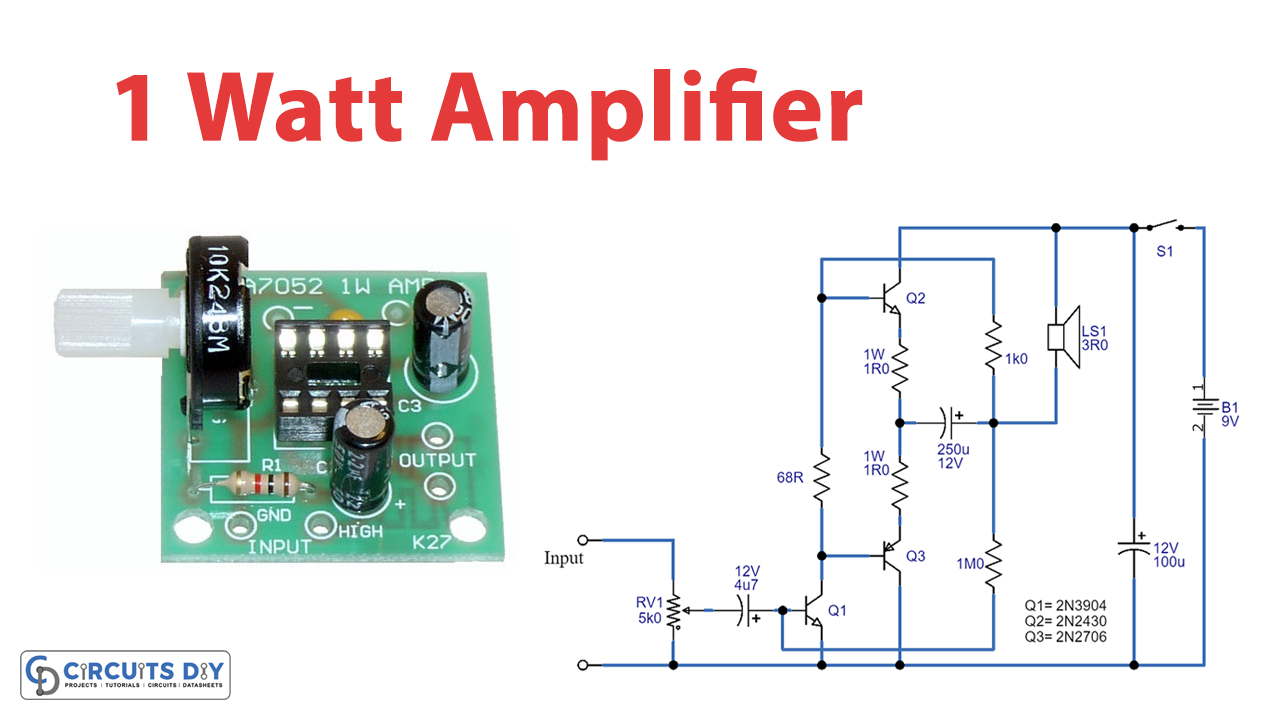
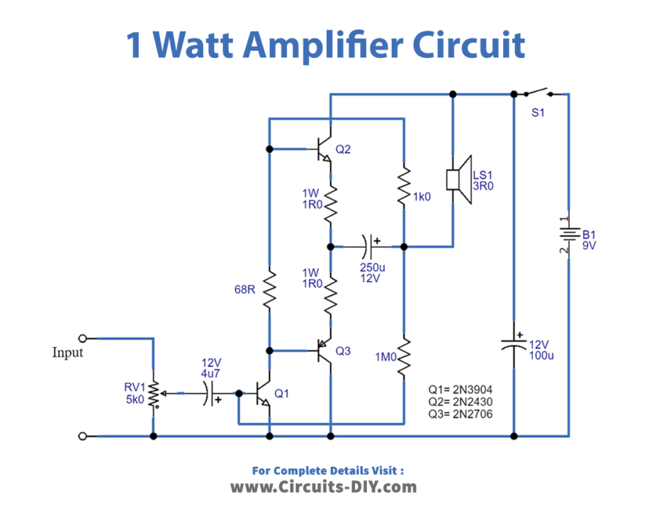
Circuit Diagram
Working Explanation
This Hi-Fi amplifier circuit utilizes a complementary output stage consisting of NPN and PNP power transistors.
Volume Control: The input signal is first passed through the volume control RV1, which acts as a volume knob. The signal then goes through C1 and is fed to the base of Q1.
Amplification: Q1 acts as the first stage amplifier, and its collector load consists of R1, R5, and the loudspeaker. The voltage at the collector is around half the supply voltage, i.e., 4V5.
The emitters of Q2 and Q3 are connected at a junction where the voltage is also close to 4V5, and R3 and R4, which are low-value resistors, restrict the current through Q2 and Q3.
Signal Switching: When the amplified input signal is less than 4V5 (around half the supply voltage), Q2 is switched off (since the base will be at a lower voltage than its emitter), but Q3 will perform. When Q1 amplifies the signal to over 4V5, the switching occurs, and Q2 performs while Q3 is switched off. The signals merge at the normal emitter junction of Q2 and Q3 and pass to the loudspeaker through the electrolytic capacitor C2.
Negative Feedback: Negative feedback is provided by resistors R5 and R2, which ensure stability by slightly reducing the gain. The circuit also includes a resistor (R1) to provide base bias for Q2 and Q3, while more modern designs use thermistors or diodes to prevent “thermal runaway,” which can damage the output transistors.
Output: The output of this 1-watt amplifier circuit is approximately 1 watt with low distortion.
Drawbacks
One potential drawback of this circuit is its DC coupling, which means that if one transistor changes, it can have a major impact on the circuit. To prevent this, it is best to use a “matched pair” of transistors for the output stage.
Final Words
We designed this circuit with stability and safety in mind, and its design has become popular in modern Hi-Fi amplifier designs. Try this circuit; we hope it will help you polish your circuit design skills. Also, feel free to ask questions about any query in the comment section. Happy learning!