In this Tutorial, we are going to make a “Very simple amplifier circuit using transistor 2N3904”. As you know an amplifier boosts or amplifies the low signals into the higher ones. Thus, this can be done in various ways, either by using different integrated circuits or by utilizing transistors. Since we are using the transistor in the circuit, so let us briefly understand its ranges and configuration.
The transistor’s operational range is divided into three ranges: When a transistor is CUT-OFF, it will stop operating; at this time, neither the base current (IB) nor the collector current will exist (IC). The transistor’s saturation range is the range of current flow from full current flow to saturation. And the flow of the stream will cease. The time frame a transistor uses to conduct current is known as the active range. It gives us the current gain.
Coming towards the configuration, here we are configuring the transistor as a common emitter. where the transistor’s base terminal acts as the input, the collector as the output, and the emitter as the common terminal.
Hardware Required
| S.no | Component | Value | Qty |
|---|---|---|---|
| 1. | NPN Transistor | 2N3904 | 2 |
| 2. | NPN Transistor | 2SC1815 | 1 |
| 3. | Resistor | 3.3M, 820K, 39K, 10K, 330 ohms | 1, 1, 1, 1, 1 |
| 4. | Electrolyte Capacitor | 1uF, 47uF, 220uF | 1, 1, 1 |
| 5. | Speaker | 0.5W | 1 |
| 6. | Battery | 6V | 1 |
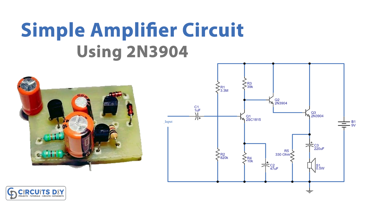
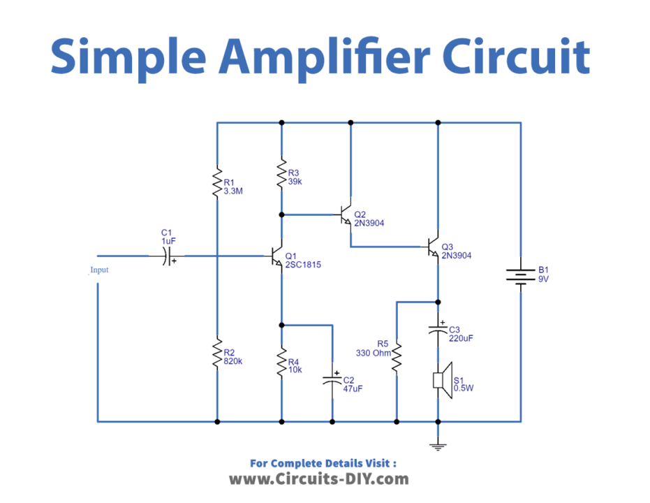
Circuit Diagram
Working Explanation
In this Simple Amplifier Circuit using Transistor 2N3904, any input signal needs to pass through capacitor C1. The input is the feed to Q1 at its base after removing all but the sound signal from the filter. The Q1 is set up as the common-emitter version of the amplifier circuit. And the voltage divider circuit for the Q1 needs to connect R1 and R2. The output signal coming from the collector of Q1 is insufficient. So, now, this signal has to be increased by Q2 and Q3 once more. The circuit includes the Darlington circuit for Q2 and Q3. It is the joining of two transistors with comparable properties. Now, the signal has better gain driven to the SP1 loudspeaker through C3 from there.
Application Uses
- Television
- Radar
- communications
- Broadcasting circuits
- Speaker and mic circuits, etc