Introduction
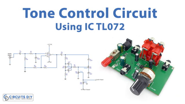
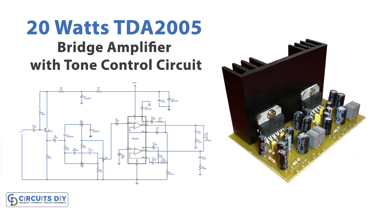
In this Tutorial, we are going to make a “20 watts TDA2005 Bridge Amplifier Project with tone control Circuit”. Tone control circuits are essentially filtered circuits that filter audio frequency signals so that only the required frequency range is allowed to pass to the amplifier and loudspeakers. This allows the listener to tailor the audio output by increasing the level of low-frequency material via bass boost or decreasing the level of high-frequency content via treble boost.
Hardware Required
| S.no | Component | Value | Qty |
|---|---|---|---|
| 1. | IC | TDA2005 | 1 |
| 2. | Resistor Different Values | – | 14 |
| 3. | Capacitor Different Values | – | 18 |
| 4. | Speaker | – | 1 |
| 5. | Transistor | BC549 | 1 |
Circuit Diagram
Working Explanation
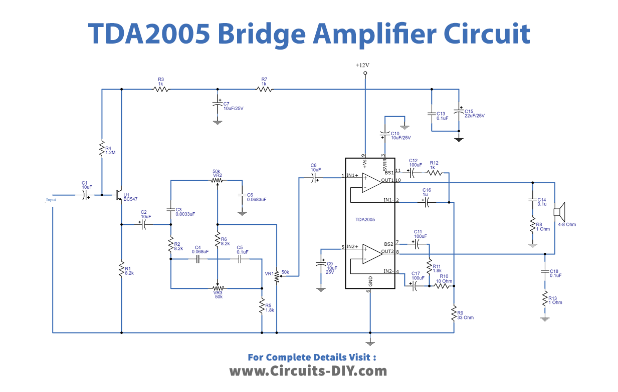
In this 20 Watts TDA2005 Bridge Amplifier Project with Tone Control Circuit, we are using TDA2005. The TDA2005’s internal construction contains two op-amps. We link them in a bridge style in this circuit. There is a lot of output power in this configuration, more than in others.
First and foremost, This circuit receives an input signal through capacitor-C1. The signal is then amplified by transistor Q1. Capacitors C2, C3, C6, and a potentiometer VR2 (Treble control) are used to modify the signal intensity or the high-frequency sound. The capacitors C4, C5, and VR3 (Bass controlling) are used to modulate the level of the bass sound. In particular, VR1 is used to change the size of the input signal. Following that, the capacitor C8 couples the signal to IC1 input-pin1 to increase the higher signal. R9, R10, and R12 together control the gain. C12 and C11 are two capacitors that increase trapping to low frequency. C17 is feedback, and the low frequency is set. A high-frequency modulating oscillator is protected by C14, R8, C18, and R13. This circuit’s output is coming from IC pins 10 and 8
Application Uses
- To filter out audio frequency
- For regulating bass and treble