
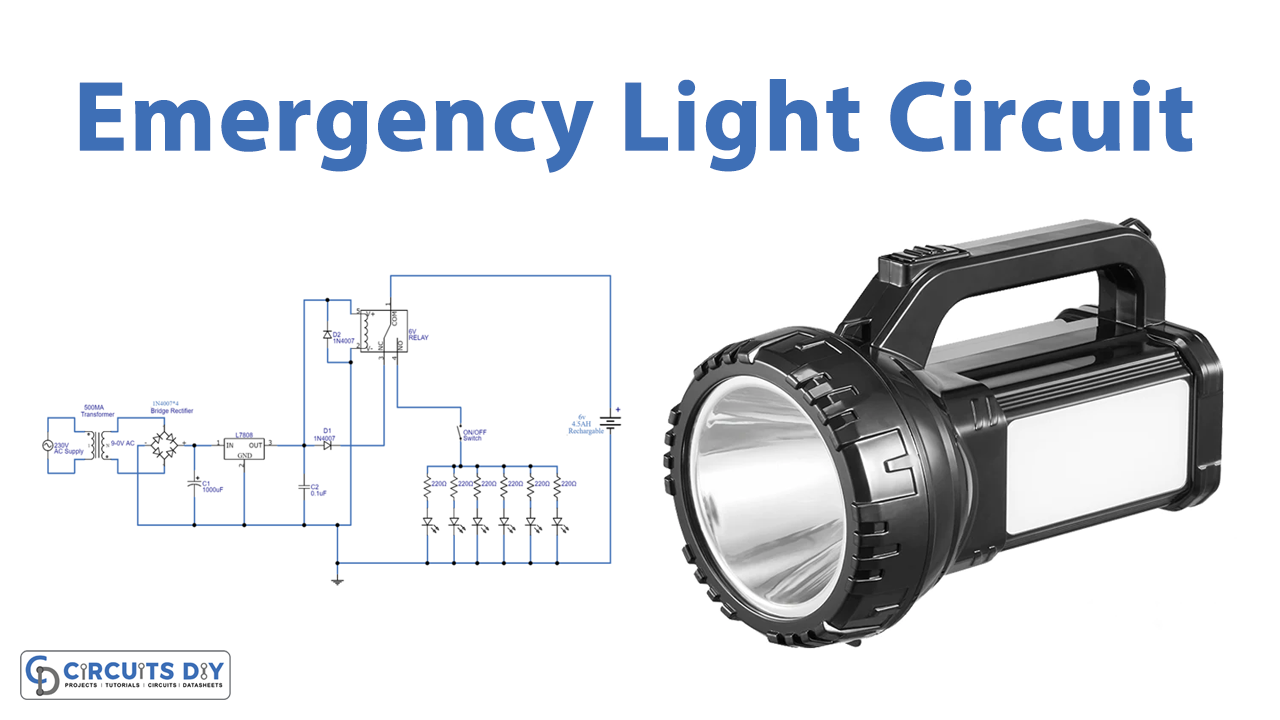
In this tutorial, we are going to make an “Emergency Light Circuit”.
In our everyday lives, power failures present a significant hindrance. As a result, we immediately lose normal lighting operations during such an outage, putting us in sudden darkness. Thankfully, an emergency light circuit provides the perfect solution to that problem. An emergency light is a circuit that automatically switches ON a battery-operated lamp as soon as the mains AC input is unavailable or during mains power failure and outages. It prevents the user from being in an inconvenient situation due to sudden darkness and helps the user to get access to an instant makeshift emergency illumination.
Here we design a simple power efficient and easy-to-construct LED emergency light circuit with few easily available components and it is very useful during a power outage or instant light needs. LEDs used in this circuit are low current high brightness white LEDs hence they will glow longer time with minimum battery power. Some emergency light circuit utilizes fluorescent tube but that will consume more power and needs to step up the voltage from battery power. The following circuit utilizes the direct supply from the battery and doesn’t need a step-up voltage stage. This turns on the light immediately once the regular source no longer distributes electricity to a lighting fixture.
Hardware Required
| S.no | Component | Value | Qty |
|---|---|---|---|
| 1. | Transformer | – | 1 |
| 2. | IC | LM7805 | 1 |
| 3. | Diode | 1N4007 | 6 |
| 4. | Resistor | – | 6 |
| 5. | Capacitor | 1000uF, 0.1uF | 1,1 |
| 6. | SPDT Relay | 6V | 1 |
| 7. | Switch | – | 1 |
| 8. | LED | – | 6 |
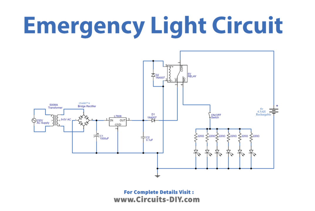
Circuit Diagram
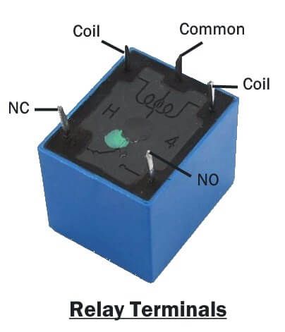
SPDT (Single Pole Double Throw) Relay
Working Explanation
As we can see in the circuit, at the first stage of the circuit we used a step-down transformer. Which converts 220v AC into 9v AC. Here bridge rectifier is the combination of 4 diodes that are used to rectify the AC into DC. Further, capacitor C1 has been used for filtration, which means removing the ripples in pulsated DC. And voltage regulator 7808 has been used to regulate the DC wave, to provide an uninterrupted and smooth 8v DC supply.
The second stage consists of the main functionality, which is to automatically switch ON the emergency light (Array of white LEDs) on power failure. We have used relay here to automate this. A rechargeable battery (6V, 4.5Ah) is connected in common with the DC supply circuit and LED array circuit with the help of SPDT (Single pole double throw) Relay. Here N/O (Normally Open) terminal of the relay is connected with the DC supply and the N/C (Normally Close) terminal of the relay is connected with an LED array. The coil terminals of the relay are connected to the DC supply, during the input AC power supply presence common terminal of the relay is attracted to N/O. And hence the battery gets DC Supply for charging. When the absence of AC input supply relay coil won’t get a DC supply and hence the common terminal is attached with N/C so the battery supply flows through the LED array and LED starts glowing. This is how emergency light works. Now when the power is restored, the relay gets activated and the lever again connects to the NO terminal which in turn disconnects the LEDs from the battery and connects the battery to the transformer for charging. Use proper polarity of rechargeable battery, the circuit involves the handling of High voltage AC supply, so handle with extreme care and use white LEDs for better light output.
Applications
Can be used in commercial and high-occupancy residential buildings, such as college dormitories, apartments, and hotels.


Sir, Digram is wrong
Please check, No and Nc conection wanted to inerchange