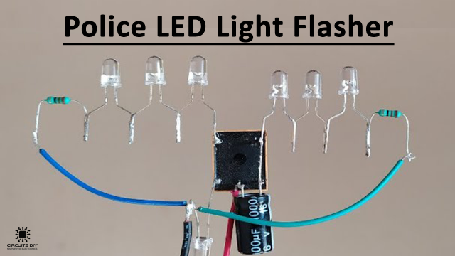
In this DIY project tutorial, we will show you how to fabricate a LED Flasher Circuit with the assistance of CD4011 IC. A LED flasher circuit is utilized to flash a single or a loop of LEDs. For example, Turns them ON or OFF.
CD4011 is the most ordinarily utilized metal-oxide-semiconductor (CMOS) chip. The IC includes 14 pins with 4 NAND gates. This IC is utilized in many instruments like Audio Docks (Portable), Audio/Visual Receivers, and Blu-Ray Players.
Here is a venture of a LED flasher circuit utilizing a CD4011 CMOS IC. The circuit flashes four LEDs, two of each at once. The number of LEDs can be expanded in equal and a limit of 12 to 15 LEDs can be utilized with every transistor.

Hardware Components
The following components are required to make LED Flasher Circuit
| S.no | Component | Value | Qty |
|---|---|---|---|
| 1. | IC | CD4011 | 1 |
| 2. | LED | – | 4 |
| 3. | Transistor | 2N4401 | 2 |
| 4. | Electrolytic Capacitors | 33µF | 2 |
| 5. | Resistor | 4.7kΩ, 1.2kΩ, 1kΩ, 470Ω | 2, 1, 2, 2 |
| 6. | Battery | 9V | 1 |
CD4011 Pinout

For a detailed description of pinout, dimension features, and specifications download the datasheet of CD4011
LED Flasher Circuit

Working Explanation
This circuit is easy to comprehend; the CD4011 IC is wired as a multivibrator in the circuit, the yields of gate B and gate D of the IC are taken care of by the transistors through 1K resistors, and every transistor is driving two LEDs through a 470 ohms current constraining resistor. The working voltage of the circuit is 9V DC. The number of LEDs can be additionally expanded by utilizing a higher NPN transistor for instance BD139 or TIP31.
Applications and Uses
The LED flasher circuit is utilized in the following areas:
- Home decorations
- Party or special occasion lighting
- Shop windows and doors
- Light indicators
- Automotive exterior and interior lighting or decoration.