Introduction
Step into the world of electronics and create your very own Simple Burglar Deterrent Circuit. With just a few essential components, you can build a device that will keep your home or office secure from intruders. Imagine the satisfaction of building something from scratch that serves a practical purpose and gives you peace of mind.
Building a Simple Burglar Deterrent Circuit is just the beginning. Not only will you learn the technical skills necessary to assemble the circuit, but you’ll also gain a greater understanding of how electronic devices work. The circuit is easy to set up, and once it’s done, you’ll be satisfied knowing that you’ve created something beneficial and practical. So why wait? So let’s get started and turn your idea of a safe space into a reality!
What is Burglar Alarm Circuit?
A burglar alarm circuit is a simple electronic circuit detecting if someone has entered a specific area without permission. This circuit can be used with ordinary door and window switches, trigger mats, and other devices that have either normally open (NO) or normally closed (NC) contacts.
Hardware Required
You will require the following hardware for Simple Burglar Deterrent Circuit.
| S.no | Component | Value | QTY |
|---|---|---|---|
| 1. | IC | SCR3N83 | 1 |
| 2. | Capacitor | 100n | 2 |
| 3. | Resistor | 680, 10m, 3K9, 100K, | 1, 1, 1, 1 |
| 4. | Transistor | – | 2 |
| 5. | Diode | 1N4148 | 1 |
| 6. | RLA | 185R | 1 |
| 7. | Switch | – | 7 |
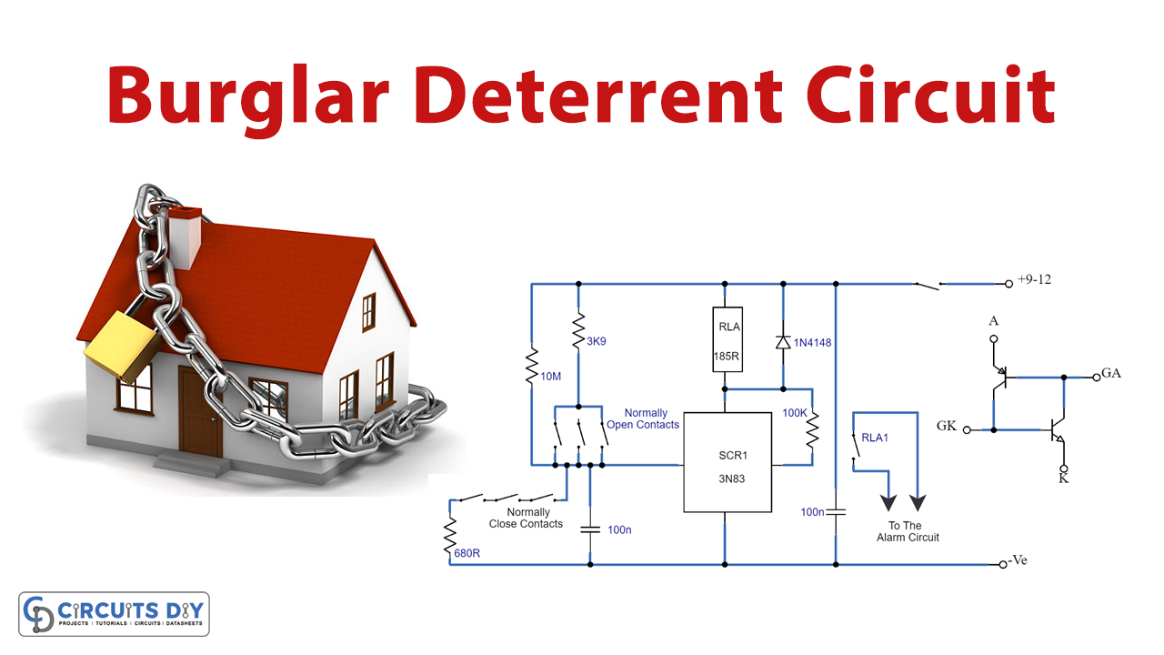
Circuit Diagram.

Working Explanation
The circuit uses a silicon-controlled switch (SCS), which is made of two transistors linked together to form a very sensitive thyristor. When the circuit is in its normal state, a resistor called R1 connects the GK terminal of the SCS to the negative supply and prevents the SCS from turning on. This means that the relay connected to the circuit will not be activated, and the alarm will not sound.
When one or more of the NC contacts are opened, the SCS receives a current through a resistor called R2 and turns on. This causes the relay to be activated and its contacts to power the alarm generator. The circuit can also be activated if one or more of the NO contacts are closed, as this will provide enough current to turn on the SCS.
Once the circuit is triggered, it can only be reset by turning off the switch SW1. This causes the current through the SCS to drop to zero and the latching action to be overcome, allowing the circuit to be ready to start again when SW1 is turned on.
Other components in the circuit, such as capacitors (C1, C2) and resistor R4, are used to prevent false alarms caused by stray electrical noise. A diode (D1) is also used to protect the circuit from high-back EMF generated by the relay coil when it is de-energized. The circuit has a standby current usage of about 1uA, which means it can be powered by normal dry cell batteries if desired.
Final Words
So you can now say that building a Simple Burglar Deterrent Circuit is a fun and rewarding experience combining hands-on learning and practical application. As you continue exploring the electronics world, you’ll discover even more exciting projects to tackle. So don’t hesitate to comment with any query, learn more, and see where it takes you!”