Introduction
Have you ever thought that how the automatic doors of stores and malls work? How does it get open when there is a person? And have you ever visited countries where street lights get ON when a person enters a certain area and you might think that how it works? The motion detector circuits are the reason behind this all. These all devices use motion detector circuits. These are the small devices that detect movement, and gestures and give signals according to the output component attached to the circuit. We would use these devices in home automation, it will save energy and will help to reduce bills. There are various motion detector circuits available. However, in this tutorial, we are going to make a “Simple PIR sensor circuit”
Hardware Required
| S.no | Component | Value | Qty |
|---|---|---|---|
| 1 | PIR sensor module | – | 1 |
| 2 | NPN Transistor | SL100, BC547 | 1 |
| 3 | Relay | 6V | 1 |
| 4 | Diode | 1N4007 | 1 |
| 5 | LED | – | 1 |
| 6 | Battery | 9v | 2, 1 |
| 7 | Resistor | 220 Ω, 10 Ω | 1, 1 |
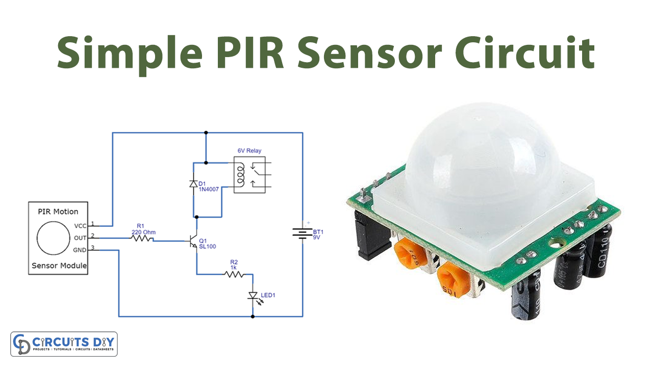
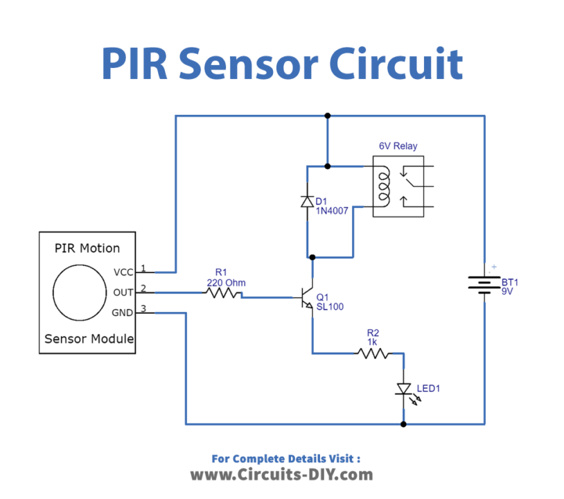
Circuit Diagram
Working Explanation
This Simple PIR sensor circuit comprises an SL 100 switching transistor, a relay, and an LED. When the sensor identifies the motion towards the surface of PIR, it then enables the current to flow through the wired switching transistor, the relay gets turned ON. You can connect the buzzer or alarm device at the output side, here we have connected the LED. This LED shows movement detection; hence it remains off when there is no detection by the PIR sensor.
Application and Uses
- Thermal sensor applications.
- Security devices.
- Automatic lighting systems.
- Motion detecting devices, etc.