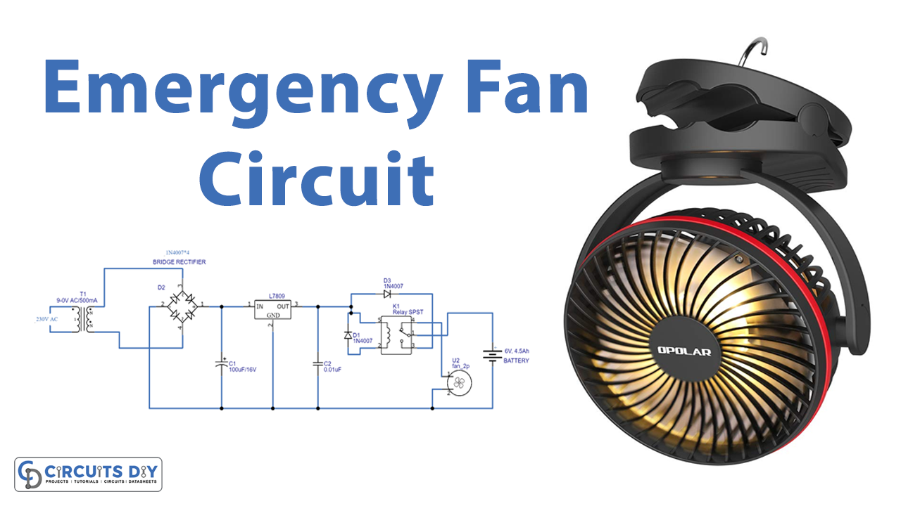
In this tutorial, we are going to make an “Emergency FAN Circuit”.
The quietest way to remove heat is with passive components such as heat sinks and heat pipes. However, these have proved insufficient in many popular consumer electronics products and they are also somewhat expensive. A good alternative is active cooling, introducing a fan into the system to generate airflow around the chassis and the heat-generating components, efficiently removing heat from the system. Here We create an emergency fan circuit by using a 9V DC fan that will help in multiple tasks. It has only a few elements very simple and easy to construct, it acts like a Battery charger circuit and DC fan circuit.
Hardware Required
| S.no | Component | Value | Qty |
|---|---|---|---|
| 1. | Transformer | 9-0 V AC | 4 |
| 2. | Diode | 1N4007 | 6 |
| 3. | Regulator IC | LM7809 | 1 |
| 4. | Relay | 9V | 1 |
| 5. | Capacitor | 1000μF/16V, 0.01μF | 1, 1 |
| 6. | DC Fan | 9V | 1 |
| 7. | Connecting Wires | – | – |
| 8. | Battery | 6V, 4.5Ah SLA | 1 |
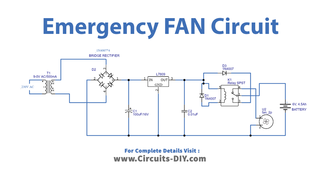
Circuit Diagram
Working Explanation
An emergency fan circuit is a multipurpose circuit, this circuit contains a bridge rectifier, Voltage Regulator, and Relay fan switch stages. Here we used a step-down transformer 230V AC to 9V AC and a bridge rectifier module (you can construct a rectifier using four 1N4007 diodes). This circuit starts with step down transformer and bridge rectifier, regulates output DC with IC7809, and then DC supply is directed to the relay coil and N/O (Normally Open contact) of a relay, the common terminal of the Relay is connected with SLA battery positive terminal, N/C (Normally Close) terminal is connected with DC Fan.
When the circuit is powered the relay coil gets energized and attracts the common terminal lever to N/O contact and makes the SLA battery charge. If the power failure occurs the relay coil is de-energized and the common terminal makes contact with N/C contact hence DC fan starts to rotate.
Applications
Can be used in electronic products.
Can be used in different places where temperature control is required.