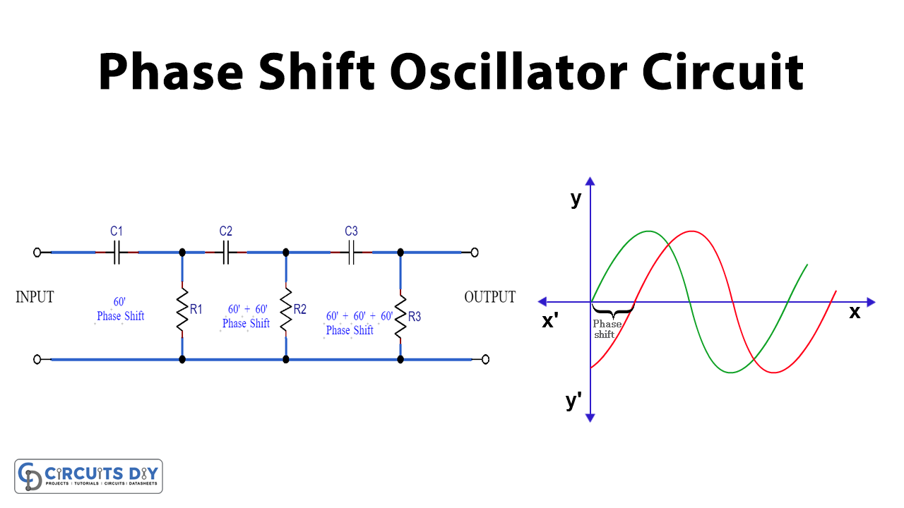
A phase Shift Oscillator Circuit is basically a phase shifter of a sine wave, A phase is a full cycle of the sine wave consisting of both positive and negative parts. Phase shifters are used to dislocate two or more sine waves which are traveling parallel at the same angle. There are many methods to shift a phase of a sine wave.
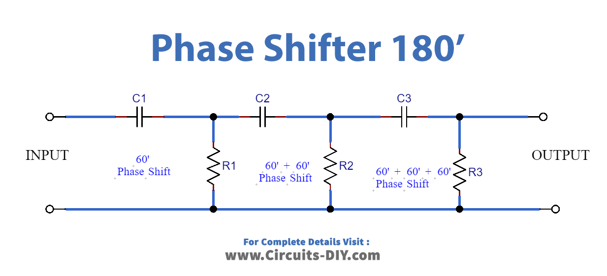
Here we will discuss the simplest one which is the RC network to shift the phase at the angle of 60° then by using the method of cascading we will invert the phase i.e. shifting it at the angle of 180°. Using this method, we can make all kinds of required shifters.
Hardware Component
The following components are required to make the Phase Shift Oscillator Circuit
| S.No | Component | Value | Qty |
|---|---|---|---|
| 1. | Breadboard | – | 1 |
| 2. | Battery | 9v | 1 |
| 3. | Connecting Wires | – | 1 |
| 4. | Capacitors | 1uF, 100uF | 3,1 |
| 5. | Resistors | 1k, 10k, 220 | 1, 2, 1 |
| 6. | DC Supply | 12v | 1 |
Phase Shift Oscillator Circuit
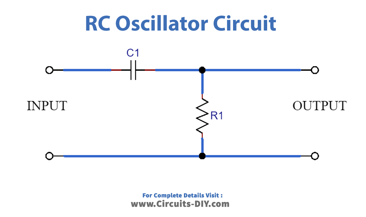
This simple circuit of the RC network will shift the phase of the input at the angle of 60°.
Working Explanation
In this circuit, the heart of the device is the RC network. 12V DC power supply is used to power the circuit. When the input passes from the first RC network, there is a phase shift of 60°. Following the second RC network, again shift of 60° will add and finally after passing through the third RC network, the phase shift becomes 180° i.e. an inverter. The output will be inverted in phase as input.
Application
- Audio oscillators
- Inverters (Sine Wave)
- Musical Instruments