Introduction
Are you tired of the same old sound from your electric guitar? Do you want to add a little “wow” factor to your music? Look no further than the treble booster circuit! With just a few simple components, this circuit can enhance your guitar’s sound by boosting the treble frequencies, resulting in a more “excellent” sound.
But don’t let the simplicity fool you—this circuit can make a big difference in your music. So let’s dive in and learn more about this super simple yet incredibly effective treble booster circuit.
What Is A Treble Booster Circuit?
A treble booster circuit is an electronic circuit commonly used with electric guitars and other electronic equipment to enhance higher-order harmonics and produce a more desirable sound. In this article, we will discuss the workings of a simple treble booster circuit and how it can improve the sound of an electric guitar.
Hardware Required
| S no | Components | Value | Qty |
|---|---|---|---|
| 1 | IC | UA741 | 1 |
| 2 | Capacitor | 1no, 47n, 470n | 1, 1, 1 |
| 3 | Resistor | 5k6, 6k8, 100k, 1k0 | 1, 1, 2, 1 |
| 4 | Switch | – | 2 |
| 5 | Polar Capacitor | 100u, 10 | 2, 1 |
Circuit Diagram
Circuit Design
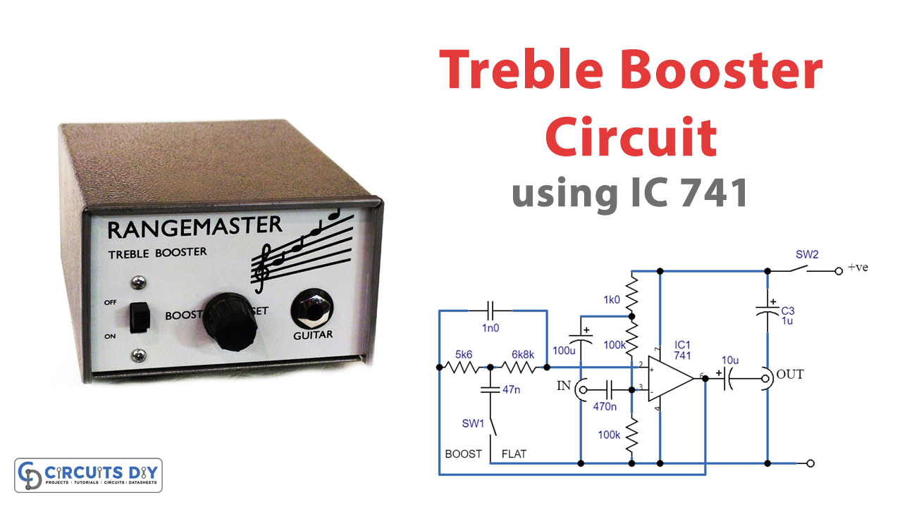
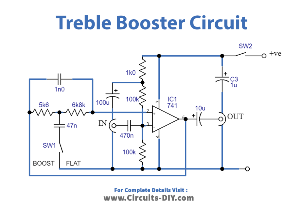
The treble booster circuit consists of an op-amp (IC1) used in the non-inverting amplifier mode. The non-inverting input is biased through a decoupling network comprising R3 and C3, while R4 and R5 provide a bias voltage to the input. C4 and C5 are used for DC blocking at the input and output, respectively.
How the Circuit Works
The treble booster circuit is a simple opamp (IC1) utilized in the non-inverting amplifier mode. The non-inverting input is biased through R4 and R5, using a decoupling network composed of R3 and C3. C4 and C5 provide DC blocking at the input and output, respectively.
When SW1 is open, there is practically 100% negative feedback via R1, R2, and C1, providing the circuit unity gain and a flat result. Pressing SW1 delivers C2 into the circuit, which decouples some of the feedback via R1 and R2 at frequencies greater than a few hundred Hz, providing the necessary, increasing reaction.
Feedback via C1 at high treble frequencies causes the response to drop away over around 5.5kHz, preventing very high-frequency harmonics from becoming overemphasized. Because the unit has unity gain at frequencies where boost is not used, it may be connected between the instrument and the amplifier.
The Importance of a Simple Amount of Focus
It is common to give just a simple amount of focus to the upper treble to provide excellent balance and a low noise level. This approach also prevents the output from sounding too unpleasant. The frequency response of this treble booster circuit is demonstrated in the associated graph.

Final Words
In summary, a treble booster circuit effectively enhances the sound of an electric guitar or other electronic equipment. With a simple opamp and a few additional components, this circuit can provide a relatively flat result at bass and many middle audio frequencies while boosting the upper middle and lower treble frequencies, resulting in an excellent sound.
So, go ahead and give it a try – we hope you like the results! And if you have any questions or comments, please let us know. Rock on!

