Introduction:
The oscillator is an electronic device or circuit that is used to generate periodic and continuous oscillations at a regular interval of time. The output signal is mainly a sine or a square wave. It is commonly used to convert the DC signal to an AC signal. There are different types of oscillators as linear oscillators, relaxation oscillators, and voltage-controlled oscillators (VCO).
A crystal oscillator is an electronic circuit that uses the crystal to select the frequency and gets the inverse piezoelectric effect. In order to achieve a highly precise frequency signal, the crystal oscillator uses the mechanical resonance of the vibrating crystal having piezoelectric properties in them. The crystal oscillators are found to be applicable in a wide variety of different applications. This post is a detailed description of the crystal oscillator.
Hardware Components
The following components are required to make Crystal Oscillator Circuits
Crystal Oscillator Circuits
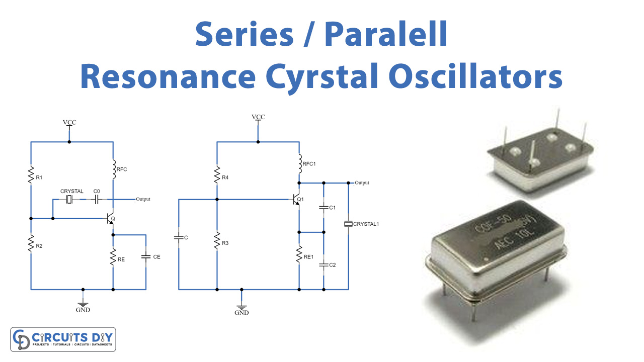
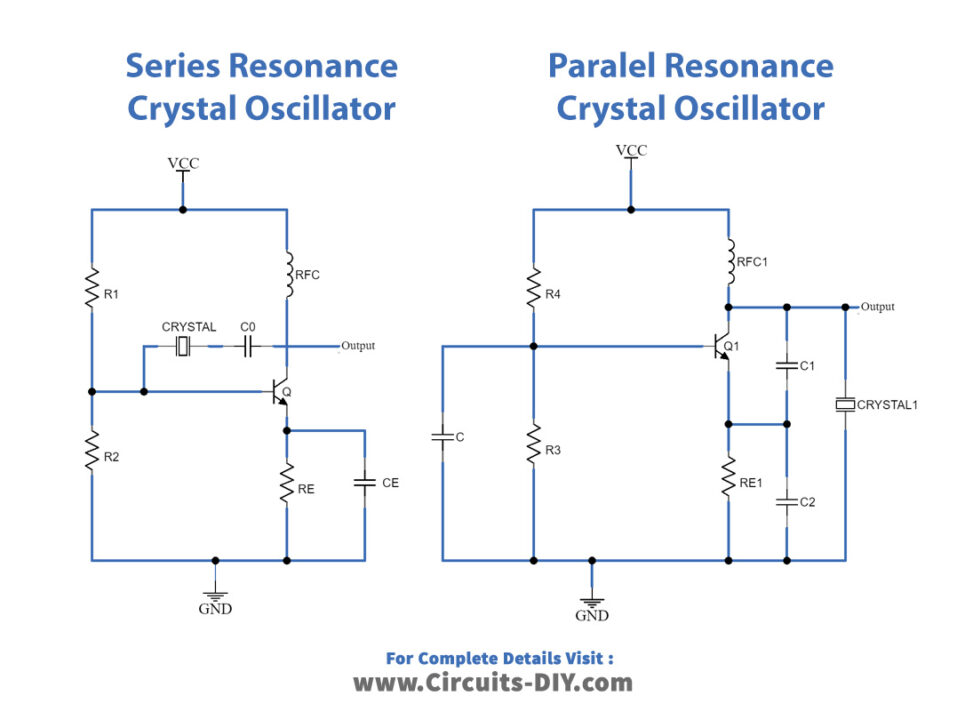
The circuit diagram for series resonance and parallel resonance circuits is given below:
Working Explanation
A solid in which the atoms or ions are arranged in a repeating pattern in three non-linear dimensions is called a crystal. The crystal is made up of an electrical transducer which is elastic in nature. Every object has a natural resonant frequency, steel is very elastic along with high sound speed and thus used in mechanical filters instead of quartz. The resonant frequency of any object is dependent on parameters like size, speed of sound, elasticity, and the shape of the crystal.
The crystal oscillator circuit operates by developing an electric field over a certain material causing mechanical deformation which is called the piezoelectric effect. Hence, the crystal oscillator generates a signal of a particular frequency by using the mechanical resonance of a vibrating crystal which is made up of piezoelectric material. Quartz oscillators are commonly used because of their compact size and good quality factor.
The quartz crystal oscillator consists of two resonant frequencies that are series resonance and parallel resonance.
Series Resonance Crystal Oscillator Circuit:
The circuit is built using a transistor in a common emitter configuration, the crystal and coupling capacitor is placed in between the base and collector terminal and the output is taken at the collector terminal.
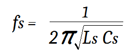
The series resonant frequency can be calculated as:
Parallel Resonance Crystal Oscillator Circuit:
To build a parallel resonance crystal oscillator, the crystal is placed in between the collector and emitter terminal while the transistor is configured in common emitter mode. The output is obtained at the collector terminal.
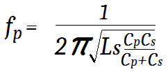
The parallel resonant frequency can be calculated as:
Applications:
The crystal oscillator is used in many applications as:
- It is used in controllers and microprocessors to provide the clock signal.
- It is used in military and aerospace devices to establish efficient communication.
- It is also applicable in numerous industrial applications like computers and instrumentation.
- Furthermore, it is used in consumer goods like personal computers, toys, cameras, video games, etc.