This project is about a basic toggle switch circuit utilizing a CD4017 IC. With this circuit, any AC or DC electronic device can work with a push button. The circuit can also be utilized in many electronic projects to actuate or deactivate the relay switch on a single pulse.
In a toggle switch, you have a lever that you go to the one side or to the next to make the current flow to the one side or to the other, or not flow by any means. There are a few kinds of toggle switches. These are described by the pole and the throw. A Pole represents a contact
The IC utilized in this circuit is an extremely famous CMOS decade counter with numerous great inherent highlights like supply voltage 3V to 15V DC, low current consumption, completely static operation, and so forth. The IC can be utilized in a wide assortment of applications from educational and home to industrial purposes.
Hardware Components
The following components are required to make Toggle Switch Circuit
| S.no | Component | Value | Qty |
|---|---|---|---|
| 1. | IC | CD4017 | 1 |
| 2. | Transistor | 2N4401 | 1 |
| 3. | DC power supply | 9 – 12V | 1 |
| 4. | Switch | – | 1 |
| 5. | Resistor | 120R, 100Ω, 390Ω, 10K | 1, 1, 1, 1, 1 |
| 6. | Power diode | 1N4001 | 1 |
| 7. | Relay | 12V | 1 |
| 8. | LED | – | 2 |
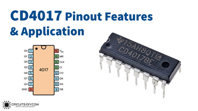
CD4017 Pinout
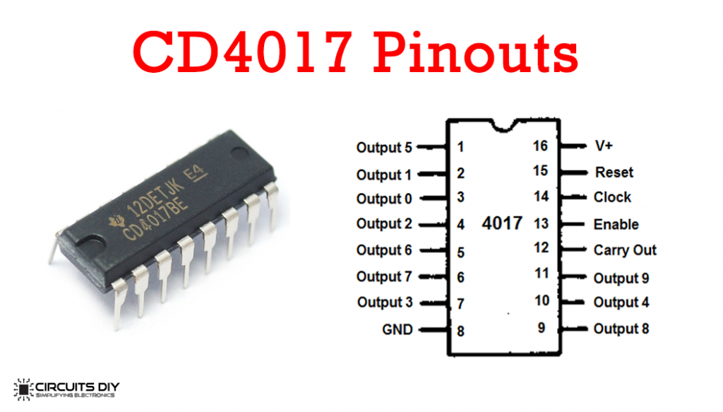
For a detailed description of pinout, dimension features, and specifications download the datasheet of CD4017
2N4401 Pinout
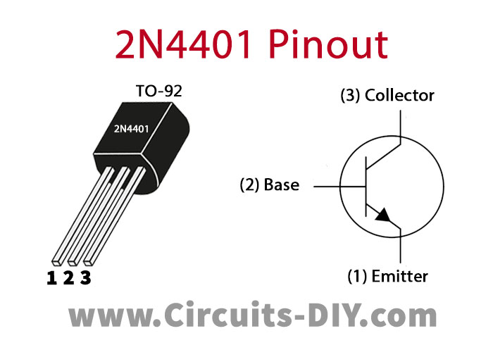
For a detailed description of pinout, dimension features, and specifications download the datasheet of 2N4401
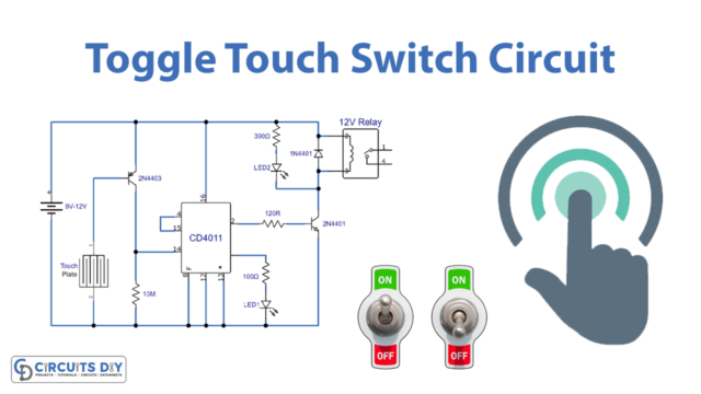
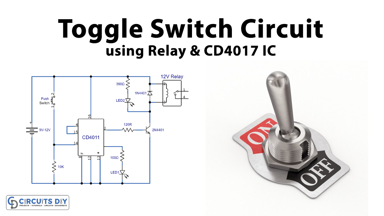
Toggle Switch Circuit
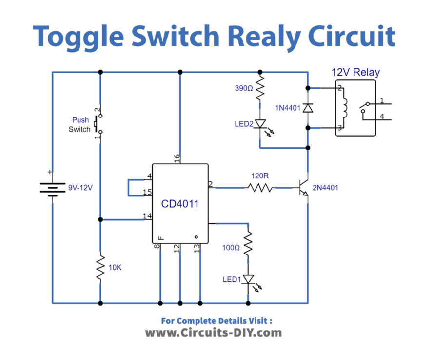
Working Explanation
The clock input pin 14 controls all the 10 output of the IC and initiate each output on a single positive pulse. In many circuits, this work finishes with a multi-vibrator circuit. But right now a CD4017 IC is utilized as a basic toggle switch in this project. So pin 13 associates with the ground to unreservedly run the IC and pin 15 associates with the second output of the IC is pin 4 to toggle switch. At the output pin 0 or pin 3, we associate a LED with a current limiting resistor when this LED activates it shows that the output at pin 3 is high or the output of pin 2 is low and the relay is not triggered / ON.
Presently on the contrary circumstance when the output at pin 2 goes high it will enact the relay through the 2N4401 transistor, and the output at pin 3 goes low and the LED 1 becomes deactivated. The yield output of the CD4017 is not sufficient to operate the relay because of which we have utilized a transistor to drive the relay.
One more LED 2 is additionally assembled with a current limiting resistor between the transistor’s line and positive supply to demonstrate the enactment of the relay.
Applications and Uses
- It is used to switch between two conditions in a circuit.
- Being simple in operation, a toggle switch can be utilized in various applications, both in business and household machines.
- Toggle Switches are used in rocker-type contact components.