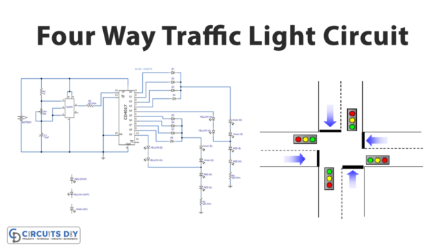
For the counting applications, CD4017 IC is considered one of the most reasonable ICs. It’s basically the IC that allows ten decoded outputs and enables to count from zero to ten. CD4017 is a CMOS decade divider or counter, having 10 output pins. That’s why this IC gets utilized in every industry including medical, electronics, automotive industry, etc. The best part is that it takes very little space in the circuits or in the devices, which makes it more promising to use. also, the IC is available at very affordable prices in the electronic market. So, in this article, we will discuss the features, pin layout, and applications of CD4017 IC.
As we discussed that IC has ten outputs and each output of this IC includes a buffer and can easily drive an LED. This buffer gate is inside the integrated circuit. Therefore no external circuits are needed for that purpose. The pulse on its input indicates it receives a low level throughout quiescent conditions. Remember, the counting can be increased by cascading the IC. For example, if the two IC get cascaded, it can count from 0 to 20. Similarly, the counting can be increased more by cascading more and more ICs. Also, CD4017 is considered great for sequential counting patterns. To make any circuit with this IC, give input power to pin 16 and ground pin number 8. Connect the output stage to the output pins, which are from pin 1 to 7 and pin 9 to 11.
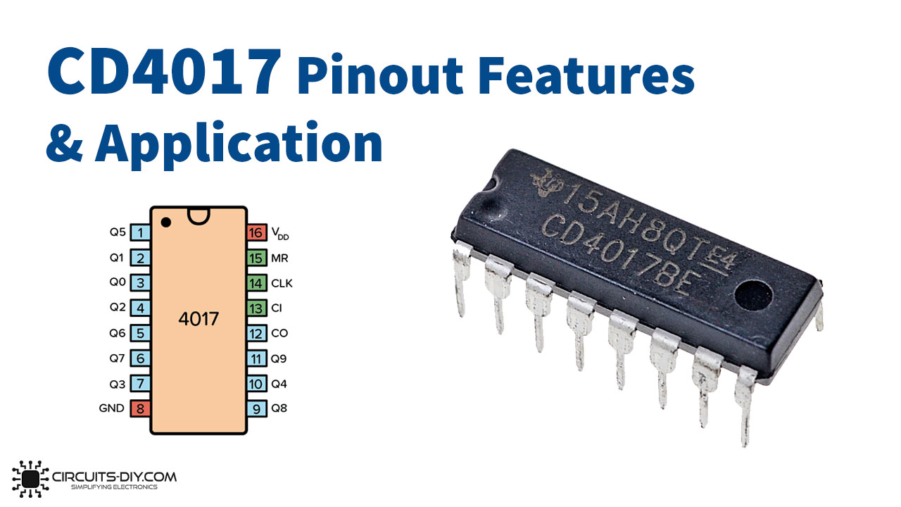
CD4017 Pinout
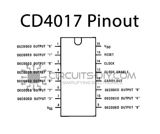
- Output Pins: from pin 1 to pin 7 and pin 9 to pin 11.
- Input Voltage pin: Pin 16 is for the applied voltage from 3V to 15V,
- Ground pin: pin 8 is for ground.
- Clock Enable Pin: Pin 13 is for the clock, when there’s logic zero, the clock gets enabled and the counter increases one count for every clock pulse. When there’s logic one, the clock input gets stopped, and the counter does nothing when the pulse arrives.
- Clock Pin: Pin 14 is the clock pin. the clock pulse must not be noisy, otherwise counter may get increased more than once
- Reset Pin: Pin 15 is a reset pin, normally it is at logic zero, when it gets one, the counter resets to zero. This pin can reset the counter and restart the counting from 0. Thus, for the normal process of a circuit, this has to be kept LOW.
CD4017 Pin Configuration
| Pin No | Pin Name | Description |
|---|---|---|
| 1 | Q5 | The output of Counter 5 |
| 2 | Q1 | The output of Counter 1 |
| 3 | Q0 | The output of Counter 0 |
| 4 | Q2 | The output of Counter 2 |
| 5 | Q6 | The output of Counter 6 |
| 6 | Q7 | The output of Counter 7 |
| 7 | Q3 | The output of Counter 3 |
| 8 | VSS | Source Supply |
| 9 | Q8 | The output of Counter 8 |
| 10 | Q4 | The output of counter 4 |
| 11 | Q9 | The output of Counter 9 |
| 12 | C-OUT | Carry Out Signal |
| 13 | CLK-EN | Clock Enable Signal |
| 14 | CLK | Clock Signal |
| 15 | R | Reset Value |
| 16 | VDD | Drain supply |
CD4017 Features
- The IC has ten decoded output pins.
- the IC is TTL compatible.
- CD4017 IC allows the voltage from 3V to 15V.
- It has an operational speed of 5MHz and a maximum clock frequency of 5.5MHz.
- Output current is 19mA.
- Power is about 10uW.
- The IC has high noise immunity.
Application
- Any counter circuit.
- Decoders.
- Binary Encounters.
- For frequency division projects.
- LED Flashing Light.
- Digital dice circuit.
- Remote control switch circuit.
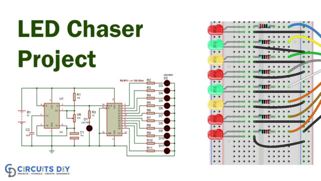
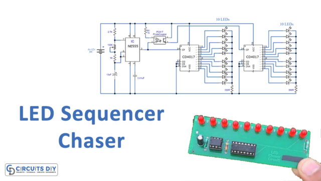
- LED chaser circuit.
- Clap on-off switch, etc.