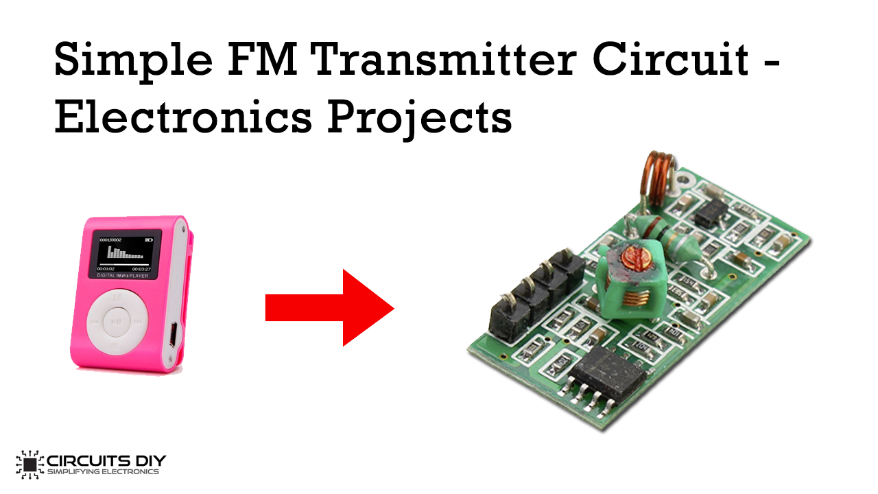
Building an FM Transmitter and broadcasting our own signals on the air is really a fun project to do. Especially, with this circuit since it does not require you to wound your own inductor or use a trimmer and spend hours tuning your circuit to make it work properly.
In this project, you will learn “How to make FM Transmitter Circuit” with suitable components and How it Works. A simple FM transmitter circuit uses Radio Frequency Transmission to transfer the medium or low-power FM signal. Its peak reach is 3 km.
Hardware Components
The following components are required to make FM Transmitter Circuit
| S.No | Component | Value | Qty |
|---|---|---|---|
| 1. | Breadboard | – | 1 |
| 2. | Electrolytic Capacitor | 1000uF | 1 |
| 3. | Battery | 9v | 1 |
| 4. | INPUT Nand Gate Schmitt Trigger | 74LS13 | 1 |
| 5. | Audio Amp IC | LM386 | 1 |
| 6. | Audio Jack | 3.5mm | 1 |
| 7. | Ceramic Capacitor | 0.1uF, 100uF, 10uF, 0.01uF, 22pF | 2, 2, 1, 1, 1 |
| 8. | Speakers For Testing | 8 ohm | 2 |
| 9. | Regulator IC | LM7805 | 1 |
| 10. | Resistor | 10 ohm, 10k | 1, 1 |
LM386 Pinout
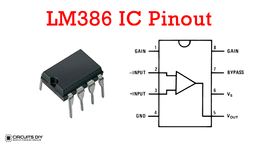
For a detailed description of pinout, dimension features, and specifications download the datasheet of LM386
LM7805 Pinout
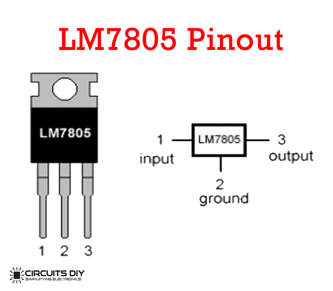
For a detailed description of pinout, dimension features, and specifications download the datasheet of LM7805
FM Transmitter Circuit
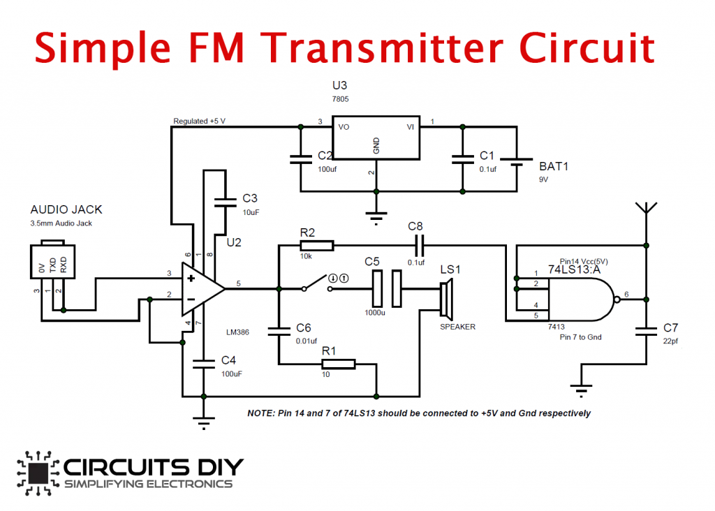
FM Transmitter Working
You can make it on a breadboard or soldered to a perf board. A 9V battery can power the complete circuit. If you use an adapter to power, make sure you add a filter capacitor to reduce the noise from switching. The circuit uses an LM386 audio amplifier that acts as a pre-amplifier; this integrated circuit amplifies the signals from the audio device and supplies them to the oscillating circuit.
The Oscillating circuit should have an Inductor and a Capacitor. In our article, the integrated circuit 74LS13, which is a 4-Input NAND gate Schmitt Trigger oscillates at 3rd order Harmonics, is around 100Mhz. A filter capacitor across the supply rails of the integrated circuit is essential to make it work.
The three terminals of the 3.5mm Audio Jack are for channel L, channel R, and Ground. You short the channel pins, so it becomes a mono channel as shown in the picture below connect it to pin three and it connects the ground to pin 2 of LM386.
You can use an 8-ohm speaker for testing the Amplifier circuit. It would be best if you disconnect the speaker while tuning the circuit.