Introduction
Have you ever played a game of toss with friends and family, only to have your fun ruined by constantly arguing over who made the winning throw? Well, fear no more! With the invention of electronic toss circuits, you can now take the guesswork out of determining a winner and add a high-tech twist to this classic game. From backyard barbecues to indoor parties, electronic toss circuits offer a fun and interactive way to bring people together and test their aim. In this blog, we’ll build the electronic toss circuit and explore how it works. So, let’s get started!
Hardware Required
You will require the following hardware for Electronic Toss Circuit.
| S.no | Components | Value | QTY |
|---|---|---|---|
| 1 | IC | 4028, 4029, 4001 | 1, 1, 1 |
| 2 | Non Polar Capacitor | 10n | 1 |
| 3 | Resistor | 1k, 100k, 1M | 1, 4, 1 |
| 4 | Switch | – | 2 |
| 5 | LEDS (D1 to D3, D5 to D7) | 5mm Red | 6 |
| 6 | LED (D4) | 5mm Green | 1 |
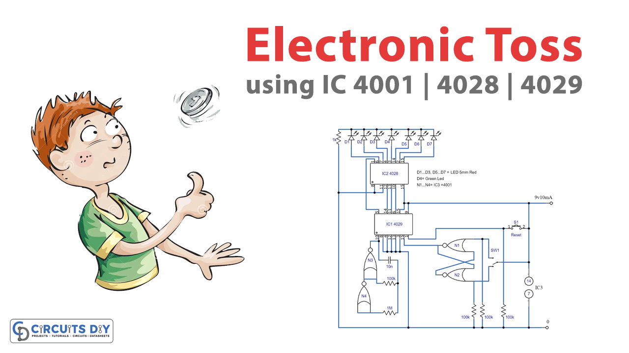
Circuit Diagram

How does the Circuit Work?
The circuit has a counter component, IC1, that returns a binary value of 0 at Q0, Q1, and Q2 outputs and a BCD-to-decimal decoder, IC2, that converts these bits to the corresponding green LED (D4) in the middle of the row. To preset the initial state of the circuit, buttons P6 to P3 are activated while connected to the ground. This signals IC1 to load 0000 as the initiating binary digits when the reset button, S1, is pressed.
Pressing the Toss Button
When the toss button, S2, is pressed, switching of N1 and N2 takes place, leading to a single pulse transition at the clock input of IC1. Based on the logic at the UP/DOWN input of IC1, the 1/8 decoder will light up D5 (on the right) or D3 (on the left), tallying with the counting up sequence from 0000 to the next binary number, 0001. When counting is downwards, a value of 1111 is delivered. In this case, IC2 will let D3 light up at the output of Q7. Since the most significant input bit of D is connected to the ground.
Guaranteed Randomness
The pulse speed applied to the counter UP/DOWN input by oscillator N3-N4 guarantees the randomness of the toss-up circuit. This ensures that the odds are personalized and cannot be tampered with.
Impeding the Counter
7 active-high outputs of IC2 are connected to their related LEDs. Q4 is used to impede the counter through the CARRY IN terminal. The counter limitation happens automatically as IC1 counts up from the state 3 output. If state 5 is concerned, the IC counts down. Both these situations allow Q4 and the CARRY-IN to go HIGH, ensuring that the counting will not continue until the reset button is pressed.
Final Words
In conclusion, the electronic coin toss circuit provides a random alternative to the traditional method of deciding who goes first or chooses their side of the field in sports games. The randomness of the circuit is guaranteed and can also be used in other random-based games. Hope you like the article. For any queries, feel free to use the comment section. We would love to help you out!