Introduction
Energy can be created from sound vibration and to understand this today in this article we have come up with a small yet informative circuit called a knock switch. To understand the working principle of the knock circuit, take the example of the knock sensor of the car which detects the high-frequency engine vibrations of knocking and sends a signal to the engine control unit (ECU). The aim is to get the maximum energy possible. But, We are making a simple knock circuit where a load of this circuit gets turned on or off by the human hand knock. Hence, the circuit is very suitable for beginner of electronics students who are also willing to research different sources of energy.
Here we are using CD4017 IC. We consider CD4017 IC one of the most reasonable counters of IC. It’s primarily the IC that provides ten decoded outputs and enables one to count from zero to ten. CD4017 is a CMOS decade divider or counter, having 10 output pins. That’s why this IC gets utilized in every industry including medical, electronics, automotive industry, etc. The best part is that it takes up very little space in the circuits or in the devices, which makes it more promising to use.
Hardware Required
| S.no | Components | Value | Qty |
|---|---|---|---|
| 1. | Decade Counter Divider IC | CD4017 | 1 |
| 2. | PNP Transistor | 2n2222 | 1 |
| 3. | Resistors | 470ohms | 2 |
| 4. | Diode | 1N4007 | 2 |
| 5. | LED | 1 | |
| 6. | Relay | 1 | |
| 7. | Piezo plate | 1 | |
| 8. | Battery | 9V | 1 |
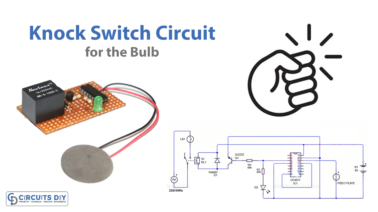
Circuit Diagram

Useful Steps
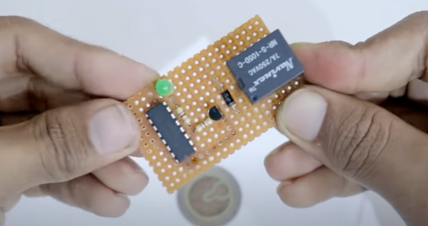
- Place the CD4017 IC and join pins 4 and 15 together

- Connect 470 ohms of the resistor to pin 3, and another 470 ohms to pin 3 to LED. Connect the positive terminal of the LED to 470 ohms and the negative terminal to pins 8, and 13 of an IC. Now connect the base of the 2n2222 transistor to the 470ohms and emitter to pins 8 and 13

- Connect the relay and the diode to the relay according to the circuit diagram.
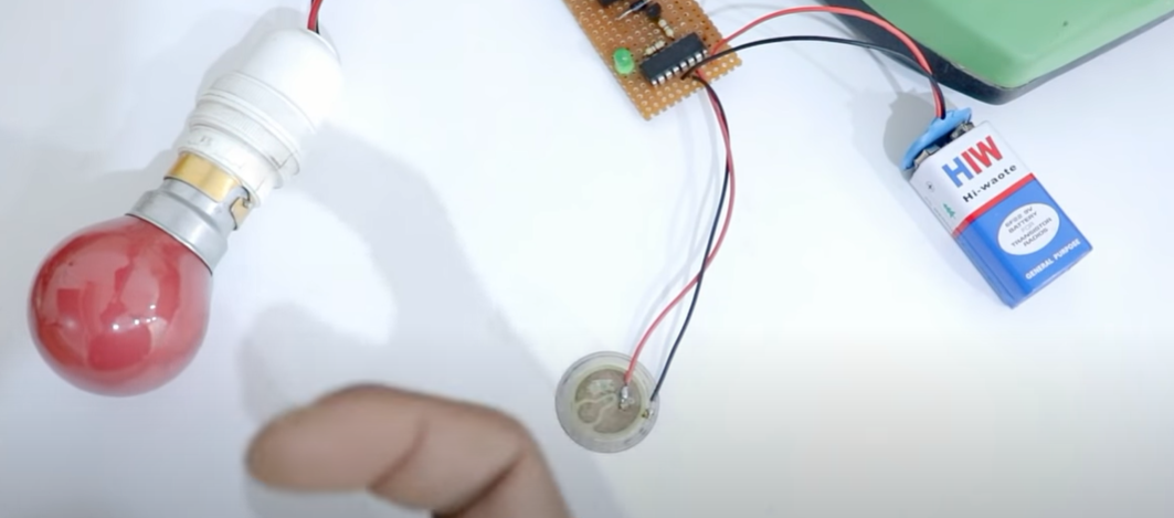
- Connect the wires on a piezo plate.
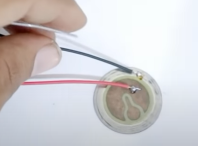
- Give positive of piezo plate to pin 14 and negative to pins 8, and 13. Give the positive of the battery supply to pin 16 and the diode’s cathode and the negative to pins 8 and 13.

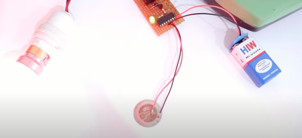
- Connect the bulb to the relay according to the diagram. When you connect the circuit to the supply, the bulb gets on. When you knock near the piezo plate, it gets off, knock again and it will on again.
Applications
- To detect the flash knocks.
- Ignition timing control.
- Automobiles.


I love this website,so educative it has every thing you need to know as a begineer