
Introduction
Don’t you think sometimes that where mathematics is used in electronics? Why do the circuit designers solve difficult maths question if there is no usage? May you be wrong. Or maybe you haven’t made any circuit that Performs mathematics in it. But don’t worry, today we are going to make a circuit that performs mathematics. Yes, we are discussing the logarithmic amplifier, which is also known as the log amplifier.
A log amplifier is a circuit that generates the output which is proportional to the logarithm of the applied input. In other words, the output voltage of the circuit is the k times of the natural logarithm of the applied input voltage.
Vout = K ln (Vin/Vref)
Hardware Required
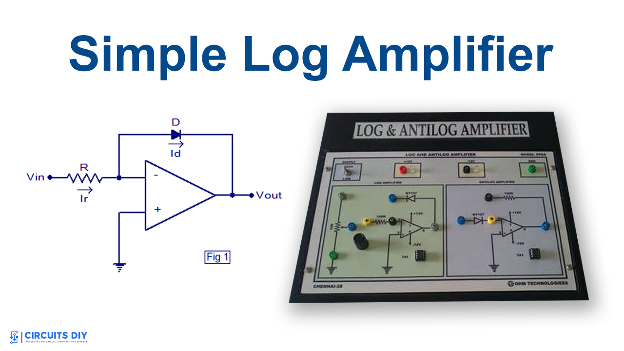
Circuit Diagram
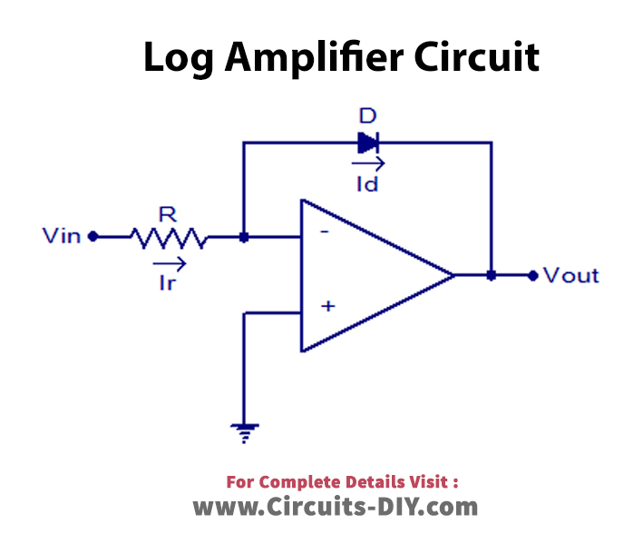
Working Explanation of the log amplifier
Opam is the central element of the circuit. It is connected as the closed-loop inverting component. It is connected with a diode in a closed-loop inverting configuration. The diode has a voltage that is proportional to the log of the current through the diode. The relation of current and voltage through a diode is:
Id= Is(e(Vd/Vt ) -1)……………………….. (a)
Where, Id= Diode Current, Is= Saturation Current, Vd= Diode voltage, Vt= Thermal voltage
But, the voltage across the diode is the positive voltage. And, thermal voltage is very less. Hence, the equation becomes:
Id= Is×e(Vd/Vt )……………………. (b)
The opam has input current Ir and it flows to the diode because there is only one path to flow. Therefore
Ir=Id…………………………….. (c)
Since, Ir=Vin/R. Therefore, Id= Vin/R.……………… (d)
By comparing b and d, it would become
Vin = Is×e(Vd/Vt )
The negative voltage of the diode is the output voltage of the circuit. After rearranging the final output equation will be
Vout = -Vt In (Vin/IsR)
Application and Uses
- For signal processing
- Utilized in compression it compression
- To detect the RMS values
- To calculate the dB value
- In RF circuits
- For automatic gain control
- In analog to digital circuits
Related posts:
 Joule Thief Voltage Booster Using a Transistor & a Toroidal Transformer
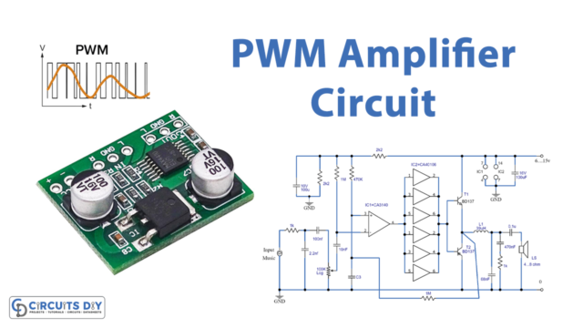 PWM Amplifier Circuit CA3130 CD40106
 High-Quality Low Noise Microphone Preamplifier Circuit Using TL071
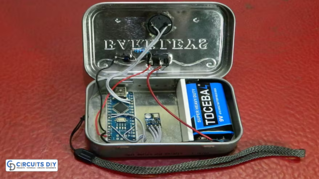 Simple Variometer for Paragliding using Arduino
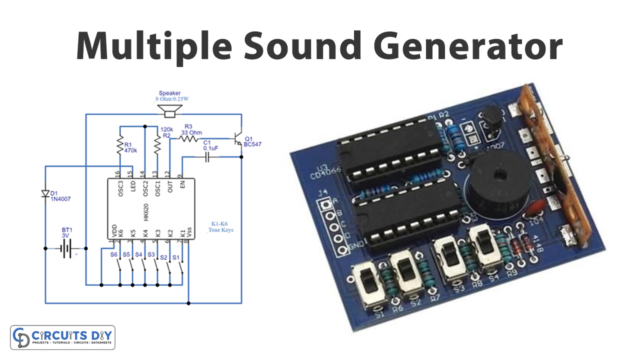 Sound Generator Circuit Using IC HK620
 LM4755 Stereo Audio Power Amplifier Circuit


