What is a Joule Thief Voltage Booster?
A Joule thief voltage booster is a circuit that translates a constant low voltage input into a periodic output of a higher voltage. Joule thief circuits can drain nearly all the energy from their attached power source, even if the power source is an almost dead single-cell battery. They are compact, low-cost, and easy to build & maintain, and are typically utilized for driving small loads such as LEDs. So, in today’s tutorial, we will understand how to design a simple Joule Thief Voltage Booster using a transistor & a toroidal transformer
A basic Joule thief configuration constitutes a DC power source, a resistor, a switching transistor, and a ferrite toroid core wrapped with two wires, with one wire coming from the positive terminal of the power source and the other through a resistor. This circuit can assist in effectively utilizing almost every ounce of energy stored in any kind of DC battery.
JLCPCB is the foremost PCB prototype & manufacturing company in china, providing us with the best service we have ever experienced regarding (Quality, Price Service & Time).
Hardware Components
The following components are required to make the Joule Thief Voltage Booster project
| S.no | Component | Value | Qty |
|---|---|---|---|
| 1. | Toroid Transformer | Ferrite core | 1 |
| 2. | Transistor | 2N2222 | 1 |
| 3. | LED | 5mm, 3.5V | 1 |
| 4. | Resistor | 1KOhm | 1 |
| 5. | Soldering Iron | 45W – 65W | 1 |
| 6. | Soldering Wire with Flux | – | 1 |
| 7. | Veroboard | – | 1 |
| 8. | DC Battery | 1.5V, AA | 1 |
| 9. | Jumper Wires | – | As per need |
2N2222 Pinout

For a detailed description of pinout, dimension features, and specifications download the datasheet of 2N2222
Useful Steps
1) Wrap two copper wires (10 Turns) around a ferrite core toroidal transformer.
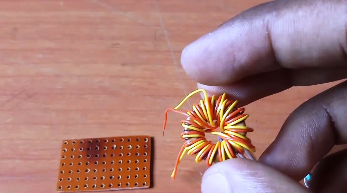
2) Solder the primary terminal of the transformer with the base terminal of the 2n2222 transistor.

3) Solder the 1K resistor between the base terminal of the transistor & the primary winding of the toroid.

4) Solder the LED array in parallel to the collector terminal of the transistor.
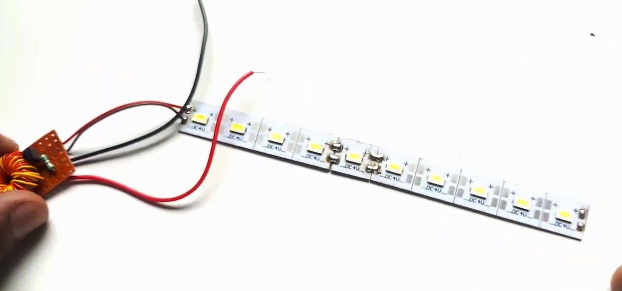
5) Power & test the circuit using any old 1.5V AA Battery.

Joule Thief Voltage Booster Circit
Working Explanation
On powering up the circuit using a nearly dead battery, a magnetic field initiates around the toroid due to the current passing through the wires. The excess current forces the 2n2222 transistor to switch off & the current to the toroid is cut off. Due to this, the magnetic field of the toroid transformer is converted into electrical energy which triggers the LEDs to glow.
As soon as the magnetic field of the toroid dies down, the 2n2222 transistor switches back on & starts draining the 1.5V AA battery for more pulses to create the magnetic field again. The frequency of voltage spikes generated by the Joule Thief circuit is over 5KHz
Applications
- Generally used in applications such as battery chargers & solar cell chargers where a low input voltage has to be increased to a useful level so that it can be used for the intended purpose.