What is an Inverter Circuit?
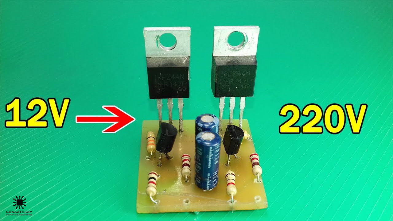
An Inverter circuit can convert a DC signal of a nominal voltage strength (9V, 12V) to a substantially higher AC signal of the desired voltage level (220V). In the event of a power failure, an inverter is very useful as a backup power unit, and if optimally charged, will also allow you to use your PC, TV, lights, power tools, appliances, and other electrical conveniences atop powering the entire house. So, in today’s tutorial, we will take a look into a step-by-step process on how you can build a Simple 12V To 220V Inverter Circuit Using two IRFZ44 MOSFETs.
This inverter circuit functions on the principle of converting a pure DC signal into a free-running square waveform, through the help of a multivibrator circuit operating in astable mode. The excess RMS voltage of the output square waveform is then chopped into the desired AC sine wave signal by using an AMV chopper such as the IRFZ44. The IRFZ44 is an N-channel fast switching MOSFET with a high drain current of 49A and a low Rds value of 17.5 MΩ.
JLCPCB is the foremost PCB prototype & manufacturing company in china, providing us with the best service we have ever experienced regarding (Quality, Price Service & Time).
Hardware Components
The following components are required to make 12V To 220V Inverter Circuit
| S.no | Component | Value | Qty |
|---|---|---|---|
| 1. | N – channel MOSFET | IRFZ44N | 2 |
| 2. | Transistor | 2SC1815 | 2 |
| 3. | Transformer | Step up/12V 3A – 220V | 1 |
| 4. | Inverter Circuit PCB | – | 1 |
| 5. | Capacitor | 10uF | 2 |
| 6. | Resistors | 1K, 330 Ohm, 220 Ohm | 6 |
| 7. | Bulb | 220V/LED | 1 |
| 8. | Soldering Iron | 45W – 65W | 1 |
| 9. | Soldering Wire with Flux | – | 1 |
| 10. | DC Battery | 12V | 1 |
| 11. | Battery clips | – | 1 |
| 12. | Jumper Wires | – | As per need |
IRFZ44 Pinout
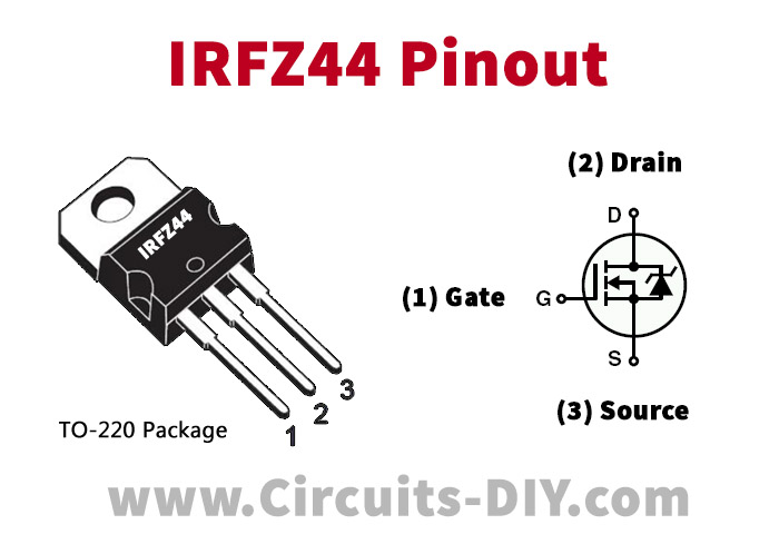
For a detailed description of pinout, dimension features, and specifications download the datasheet of IRFZ44
Useful Steps
1) Design the PCB layout for the inverter using any PCB CAD tool. To learn more about the latest Free PCB CAD tools of 2020 please refer to our previous article by clicking here.

2) Solder all the components on the PCB board.

3) Solder two wires with an output of the IRFZ44 MOSFETs & another with the output of the 220 Ohm voltage divider circuit.
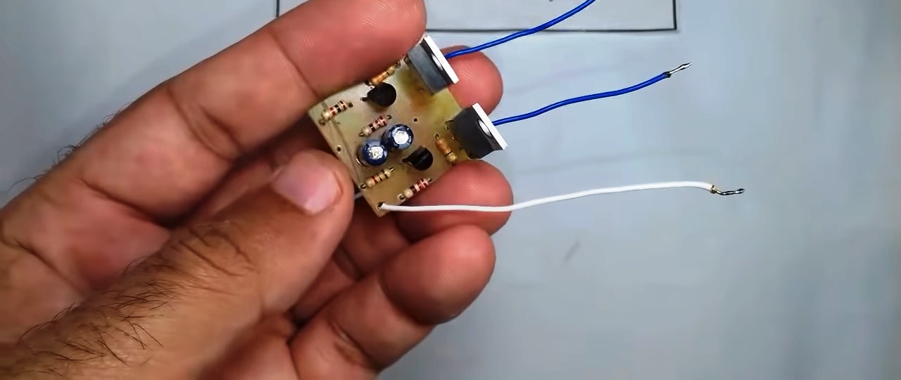
4) Solder the Battery clip (wires).
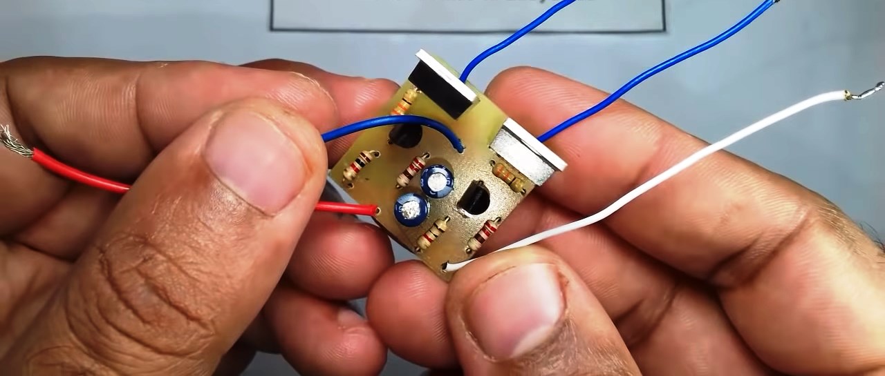
5) Solder the Output of the inverter circuit with a Step up CT Transformer.

6) Power up & test the circuit using a 220V LED Bulb.

12V To 220V Inverter Circuit
Working Explanation
This circuit uses a multivibrator circuit running in astable mode to generate a free-running square wave. On powering on the circuit using a 12V Battery, a square wave signal is generated by the multivibrator circuit, but, in order to run an AC device without any issues, we require a pure AC sine wave signal.
This is achieved by feeding the square wave output of the multivibrator circuit to two IRFZ44 MOSFETs, this chops up the excess RMS voltage of the square waveform output into a somewhat noisy sine wave signal. The output sine wave signal is then fed to a 12V to 220V step-up transformer, which bumps up the voltage to the desirable AC level of 220V. You can connect an LC configuration in parallel to the output of the transformer to further reduce the noise & improve the waveform of the AC output signal.
Applications
- They are used by devices such as Centrifugal fans, pumps, mixers, extruders, and test stands. conveyors, metering pumps. and Web-handling equipment