Introduction
Horseback riding is a beloved sport, a means of transportation, and a way of life for many people worldwide. Horses are majestic creatures that move in unique and rhythmic patterns, each step and pace telling their own story. If you’re a horse lover, you’ll know how important it is to understand your horse’s pace, whether walking, trotting, cantering, or galloping. But have you ever wondered what it would be like to hear those paces as if you were riding on the horse’s back?
This blog introduces you to a super creative and exciting project, the Horse Pace Sound Simulator Circuit, which will allow you to experience your horse’s paces in real time!
Overview
In horseback riding, it’s crucial to have an understanding of the horse’s foot movements. To achieve this, a simple electronic circuit using LEDs can indicate the idealized pattern of the horse’s footsteps and show when each foot makes contact with the ground. Although the circuit is uncomplicated, it has several impressive features. Each horse moves slightly differently based on factors such as age and training, so this circuit serves as a fascinating model for how a horse gallops.
Hardware Required
| S.no | Components | Value | Qty |
|---|---|---|---|
| 1 | IC | NE555, CD4017 | 1, 1 |
| 2 | Capacitor | 10, 100uF | 1, 2 |
| 3 | Resistor | 1k, 560 | 8, 4 |
| 4 | Variable Resistor | 5k | 1 |
| 5 | Transistor | BC547B | 4 |
| 6 | Diode | 1N4148 | 4 |
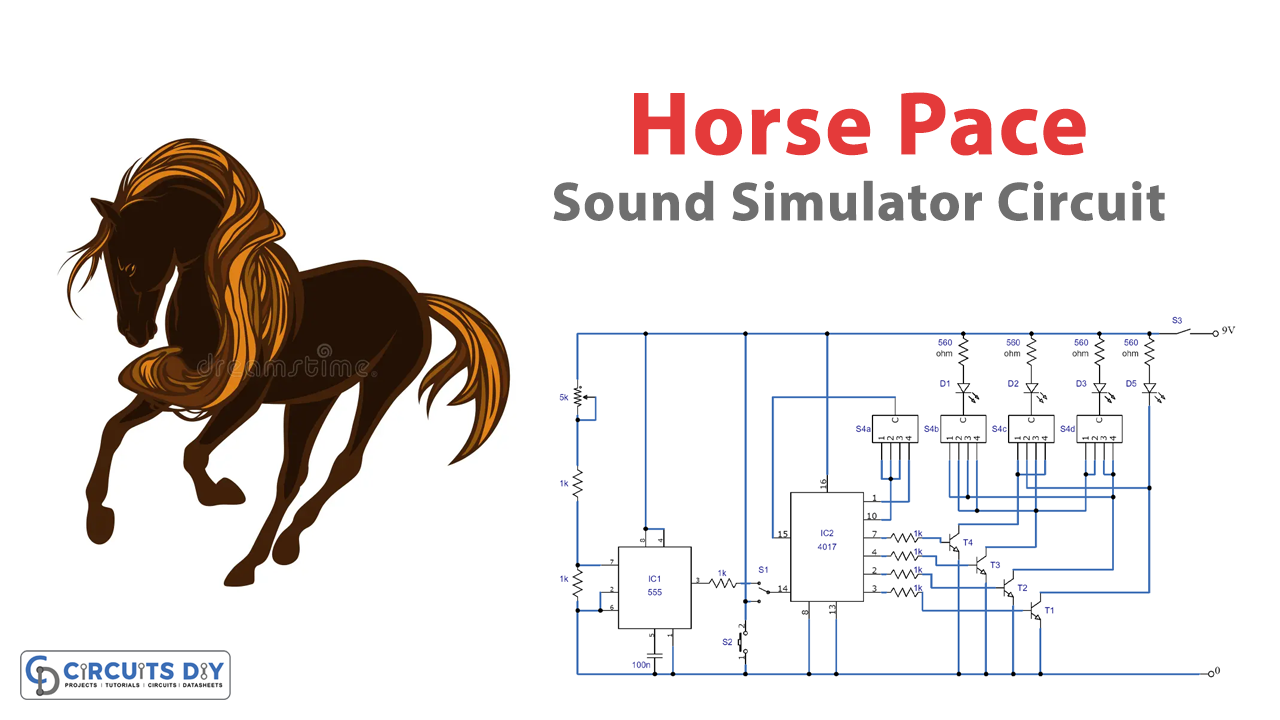
Circuit Diagram

Circuit Explanation
The circuit comprises a counter (lC2) and a 555 timer (IC1). The 555 timer provides a clock signal, which we can adjust by changing P1 to determine the speed at which the string of lighting LEDs illuminates. The counter keeps track of the sequence and provides output signals on pins 2, 3, 4, and 7. These outputs are connected to driver transistors T1 through T4, whose open collectors are linked to an encoding module.
The encoding module’s design determines which LEDs light up at a given time. We can create four different encoding modules representing four distinct sequences: walk, trot, canter, and gallop. Each module can be designed differently and attached to the control board as an independent unit or enclosed into the control unit printed circuit board and switched using a 4-pole, 4-way switch.
How the LEDs Light
Each encoding module comprises wiring with a unique layout. Each counter output turns high (logic “1”) in succession, causing the correct transistors to activate, which powers the LEDs D1 through D4. Switch S1 determines whether the circuit operates in clock-controlled or step-by-step mode, while switch S2 is used to advance to the next step in the latter scenario.
D1 represents the right front leg, D2 the left front, D3 the left back, and D4 the right back leg.
Working
The circuit uses a single LED for each horse’s four feet, lighting up the LED when the corresponding foot is on the ground. The circuit simulates the four distinct gaits of a horse: walking, trotting, cantering, and galloping, with each gait lighting up the LEDs in a unique pattern. Additionally, we can adjust the speed at which the LEDs light up, and a “one step at a time” mode is also available.
Final Words
The Horse Pace, Sound Simulator Circuit, is an excellent example of how we can use technology to simulate real-life scenarios. With its ability to accurately depict the sounds and rhythms of a horse’s gait, this circuit is a valuable tool for horse riders and enthusiasts alike. Whether you are a seasoned equestrian or a beginner looking to improve your riding skills, this circuit is a must-try. We hope that you have found this article informative and that it has inspired you to try your hand at building your own Horse Pace Sound Simulator Circuit. Good luck and happy riding!