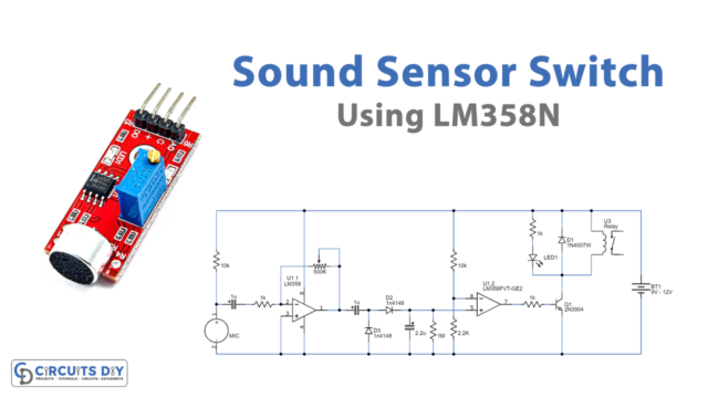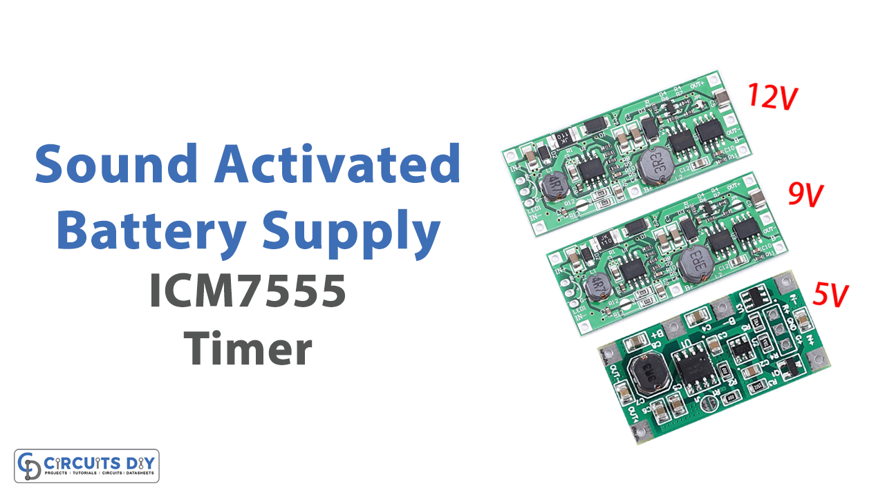
Dynamic control through sound is an extremely helpful application of electronics. We use this phenomenon every day in many different devices such as sound-activated doors, locks, switches & assistive devices. So, in this project, we are going to design a Sound Activated Adjustable Battery Supply Using ICM7555 precision Timer IC.
The main component of this Sound Activated Adjustable Battery Supply circuit is an ICM7555 timer. ICM7555 is a CMOS timer that can provide significantly higher performance than the standard NE/SE555 timer. The IC offers features such as low supply current, wide operating supply voltage range, low threshold, Trigger, and Reset currents, no crowbarring of the supply current during output transitions, higher frequency performance, and no requirement to decouple control voltage for stable operation.
Hardware Required
You will need the following parts to build this project
| S.no | Component | Value | Qty |
|---|---|---|---|
| 1. | Timer IC | ICM7555 | 1 |
| 2. | Counter IC | CD4017 | 1 |
| 3. | NPN Darlington Transistor | TIP120 | 1 |
| 4. | Voltage Regulator | LM317T | 1 |
| 5. | Electret mic | – | 1 |
| 6.. | NPN Transistor | 2N4401 | 2 |
| 7 | LED | 5mm, red | 1 |
| 8. | Diode | 1N4007 | 2 |
| 9. | Potentiometer | 1M Ohms, 5K Ohms | 1 |
| 10. | Resistor | 1M, 10K, 1K, 470 Ohms, 240 Ohms, 120 Ohms | 10 |
| 11. | Capacitor | 100uF/50V, 10uF/50V, 4.7uF, 1uF/50V, 0.1uF, 100nF | 7 |
| 12. | DC Battery | 12V | 1 |
| 13. | Battery Clips | – | 1 |
| 14. | Breadboard | – | 1 |
| 15. | Jumper Wires | – | As per need |
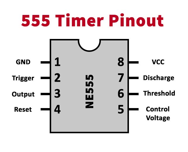
| Pin Name | Pin No. | Description |
|---|---|---|
| GND | 1 | Ground |
| TRIG | 2 | Trigger, set to 1/3 of Vcc |
| OUT | 3 | Timer Output |
| RESET | 4 | Reset active low |
| CONT | 5 | Comparator threshold control |
| THRES | 6 | Threshold, set to 2/3 of Vcc |
| DISCH | 7 | The low-impedance discharge path |
| Vcc | 8 | Chip supply voltages (6v-12v) |
Circuit Diagram

Working Explanation
A sound input (usually by clapping or hitting any random surface) is taken as an input to the circuit through an electret mic. Here, a capacitor (50uF) blocks the DC component of the audio, allowing only the AC component to flow to the base of the transistor Q1 (2N4401) as a control signal. the output from the transistor serves as the control signal for transistor Q2. The amped output from the transistor serves as an input to pin 2 of the timer & defines the trigger voltage (1/3rd of Vcc) for the IMC7555 IC.
The square wave output from the timer IC serves as the input to the CD4017 through CLK pin 14. The counter output Pin (Q1) acts as a control signal to the base of the TIP120 NPN Darlington pair transistor. Here, we are using a Darlington pair because of its high current gain (hfe = 1000) and high collector current (IC =5A) making it suitable to control loads with high current. The emitter output linked to the 12V DC supply serves as the input to the LM317T regulator, which ensures a constant current output. The output of the LM317T can be adjusted by a 5K pot at the ADJ pin. Use proper heatsinks with TIP120 7 and all other ICs.
Applications
- Power supplies with dynamic control functionality have a wide variety of uses in places such as the telecom industry, automotive industry & consumer electronics.