Pulsating LED circuit is a small electronic project functioning ON and OFF of LEDs. This circuit includes the timer IC NE555 along with a transistor.

Hardware Components
The following components are required to make Fading LED Circuit
| S.no | Component | Value | Qty |
|---|---|---|---|
| 1. | Transistor | 2N4403 | 1 |
| 2. | IC | NE555 Timer | 1 |
| 3. | Resistor | 390Ω, 1KΩ, 10KΩ | 1,1,1 |
| 4. | Variable resistor | 1MΩ | 1 |
| 5. | Battery | 9V to 12V | |
| 6. | Capacitors | 100µF, 3.3µF | 1,1 |
| 7. | LED | – | 1 |
NE555 IC Pinout

For a detailed description of pinout, dimension features, and specifications download the datasheet of 555 Timer
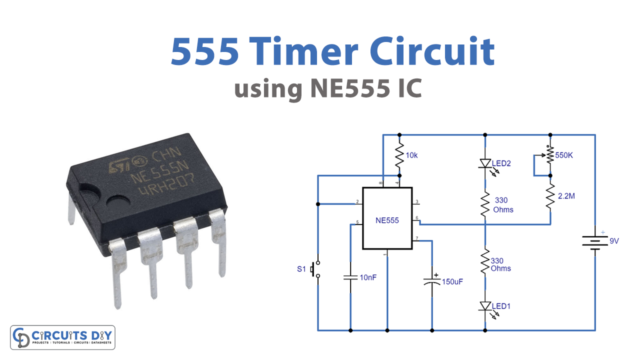
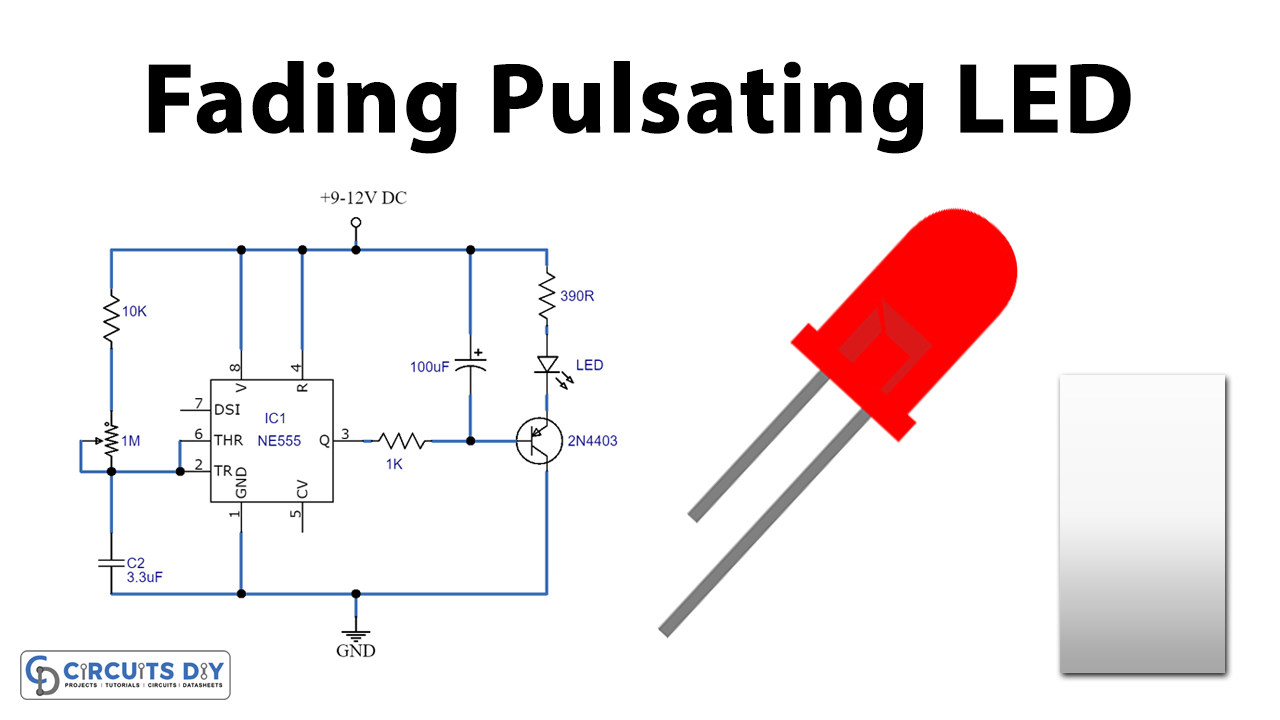
Fading LED Circuit
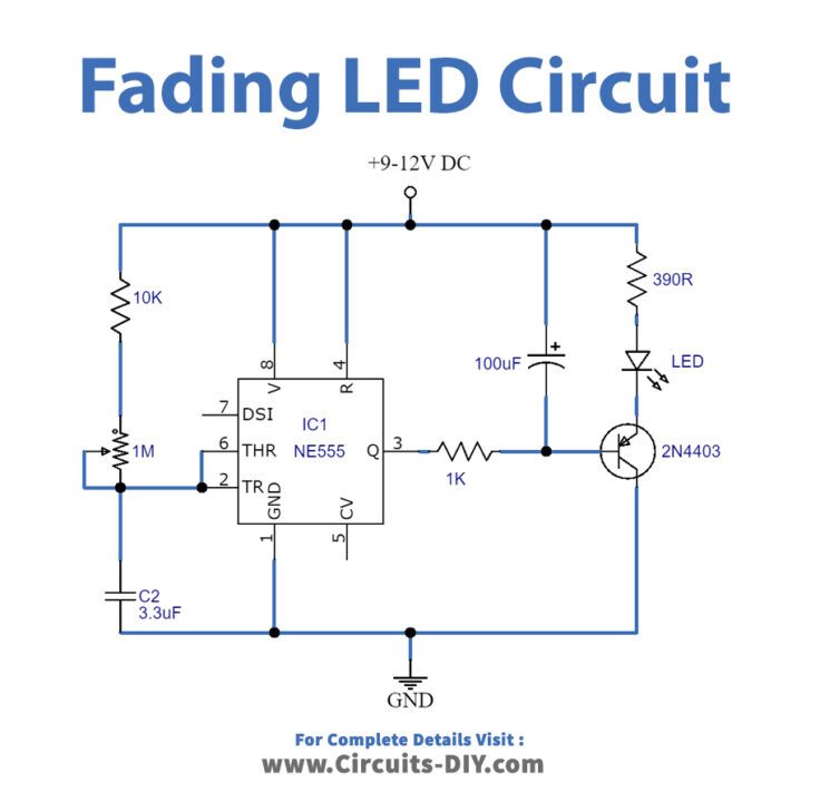
Working Explanation
The timer IC NE555 plays the main role in the circuit. It is working in its astable multivibrator form. An astable multivibrator is a free-running multivibrator form that produces continuous rectangular waveforms without the help of external triggering. NE555 generates timed pulses that are responsible for the fade-in fade out of the LEDs. For this case, a 1MΩ variable resistor in the circuit helps adjust this delay in fading of LEDs. Fading of the LEDs also depends on the 100uF electrolytic capacitor. Moreover, the transistor in the circuit amplifies the signal enough to light up an LED.
The operating voltage of the overall circuit is 9V to 12V. Furthermore, any LED of 25mA current rating is feasible to connect to the circuit. Also, to further add more LEDs connect LEDs in parallel connection with 390Ω of resistor with each connection. Similarly, connect, in series, three LEDs with a 68Ω resistor for a 12V DC power supply.
Application
LED Strip lights in festivals and functions.