Today in this post we will discuss the top 3 simple timer circuits. A timer switch or timer circuit is a timer to control any electronic switches or circuits by a timing mechanism. Here, the timer is a very simple circuit, working by using just one or a pair of transistors. this circuit serves its purpose of time delays operation of a device. The timer circuit is made with a number of different schematics which are explained as follows.
Hardware Components
The following components are required to make Timer Circuits
| S.no | Component | Value | Qty |
|---|---|---|---|
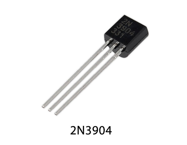
| 1. | Transistor | 2N3904, BC517 | 3, 3 |
| 2. | Wires | – | 1 |
| 3. | SPDT Relay | 12V | 3 |
| 4. | Power Supply | 12V | 1 |
| 5. | Push button | – | 3 |
| 6. | Diode | 1N4007 | 3 |
| 7. | Resistor | 47KΩ, 470KΩ | 3,3 |
| 8. | Capacitor | 470µF, 1000µF | 3,3 |
2N3904 Pinout
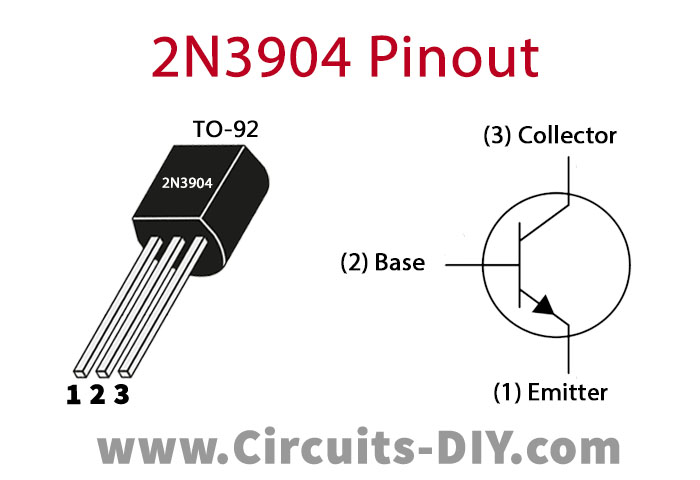
For a detailed description of pinout, dimension features, and specifications download the datasheet of 2N3904
BC517 Pinout
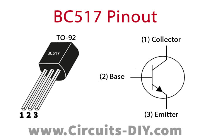
For a detailed description of pinout, dimension features, and specifications download the datasheet of BC517
Working Explanation
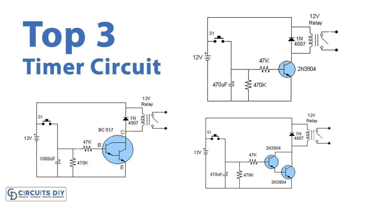
Using a Single Transistor
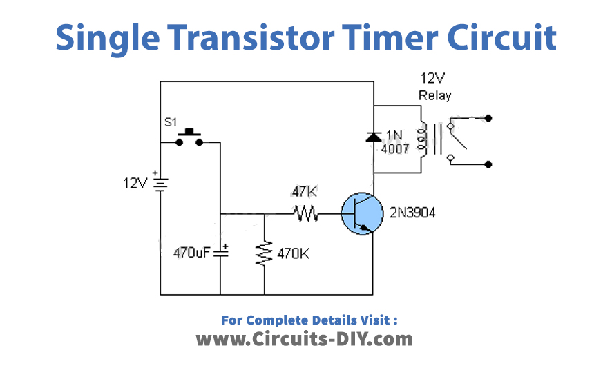
This timer circuit uses only a single 2N3904 transistor. When the switch is turned ON, the transistor activates the relay, thus turning the circuit ON for a time duration. The relay is operational for a period of time and is set using the electrolytic capacitor. Additionally, using a 470µF capacitor the relay operates for about 45 seconds. Moreover, by increasing the value of the capacitor to 1000µF the ON time duration rises to 2.5 minutes.
Using a Pair of Transistors
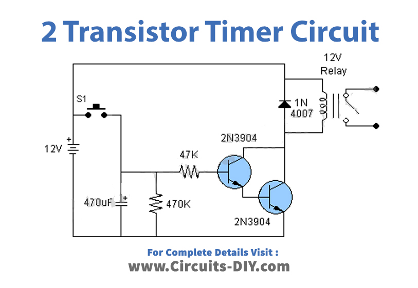
Two 2N3904 transistors double the time duration. These transistors together act as a Darlington pair. This circuit is such that using a capacitor of 470µF the time is 90 seconds. This time period is double in value as that of the first circuit. Similarly, the time duration of 5 minutes is gained through a 1000µF capacitor.
Using a Darlington pair
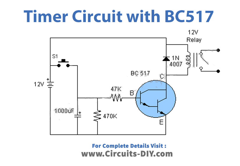
A Darlington pair is a single transistor that provides a large gain as that of two transistors. Here, for the timer circuit, two transistors are replaced with a single BC517 Darlington pair. This circuit has much simple circuitry and double-times duration as that of the second circuit.
The operating voltage of all three circuits is 12V. To operate the circuit at a low voltage of 5-6V, the relay with the same voltage rating has to be selected.
Application
- All the circuits or devices involving clock timings use timer circuits. The basic application of timer circuits includes timer alarms and automation purposes such as street lighting where lights need to turn ON for a specified period of time.