In this tutorial, we are going to make a “Solenoid Driver Circuit”.
A Solenoid is an electromagnetic device that converts electrical energy into mechanical energy, it converts electric supply into linear motion by the magnetic field. As solenoids are very commonly used actuators in many process automation systems. Although there are many types of solenoid mechanisms available, the most basic thing remains the same. That is, it has a coil wound over a metal (conductive) material. When the coil is energized, this conductive material is subjected to some mechanical movement which is then reversed through a spring or other mechanism when de-energized. Since the solenoid involves the coil, they often consume a large amount of current.
So, it requires a regulated DC supply with constant current due to the presence of electromagnetic coil and mechanical parts. All these things make it mandatory to have some type of driver circuit to operate it. Here we design a simple solenoid driver circuit by using a single NPN transistor. A 12V Solenoid device is used here and it is driven by NPN transistor TIP120. This transistor gives a better switch response at high voltage and current.
Hardware Components
The following components are required to make Solenoid Driver Circuit
| S.no | Component | Value | Qty |
|---|---|---|---|
| 1. | Solenoid | 12V | 1 |
| 2. | Transistor | TIP120 | 1 |
| 3. | Voltage Regulator IC | 7805 | 1 |
| 4. | Diode | 1N4007 | 1 |
| 5. | Capacitor | 0.1µF | 1 |
| 6. | Resistor | 2.2KΩ, 4.7KΩ | 1,1 |
| 7. | Switch | – | 1 |
| 8. | Connecting Wires | – | 1 |
| 9. | Power Supply | 12V | 1 |
TIP120 Pinout
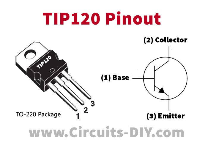
For a detailed description of pinout, dimension features, and specifications download the datasheet of TIP120
7805 Pinout
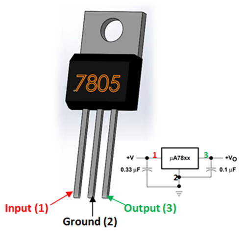
For a detailed description of pinout, dimension features, and specifications download the datasheet of 7805
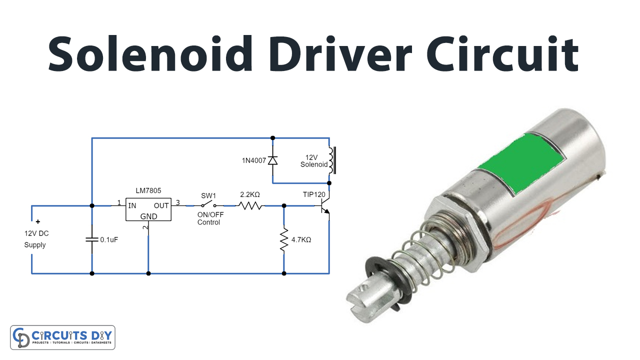
Solenoid Driver Circuit
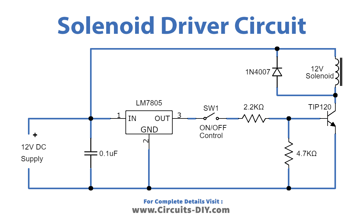
Working Explanation
The solenoid draws a continuous current of 700mA when energized and a peak of nearly 1.2A so we have to consider these things while designing the driver circuit for this particular Solenoid valve. By using a few easily available components we can build this simple solenoid driver circuit. A solenoid can simply be turned on by powering 12V across its terminals and turned off by powering it off. To control this, turn ON and OFF process we need to use a switching device as Transistor TIP120. Transistor Q1 requires minimum base voltage hence voltage regulator IC 7805 is used to regulate the input DC voltage. Input supply 12V is directly applied to the solenoid device and another end terminal of the solenoid is connected with the Q1 transistor collector terminal. The regulator output is connected with the base of Q1 through the ON / OFF control switch.
When the switch is in OFF condition then the Q1 transistor stays in OFF condition and the solenoid cannot get supply. When the switch is in ON condition then the Q1 transistor becomes ON state due to the base-emitter voltage and solenoid coil getting supply and then becomes electromagnet then mechanical lever feels linear motion. By using this simple solenoid driver circuit, we can control current and voltage flow in the solenoid device.
Applications
Solenoid devices are widely used in different industries, starting from simple locking devices, Automotive gearbox, air conditioners, clamping devices, medical equipment, agricultural systems, solenoid valves, etc.