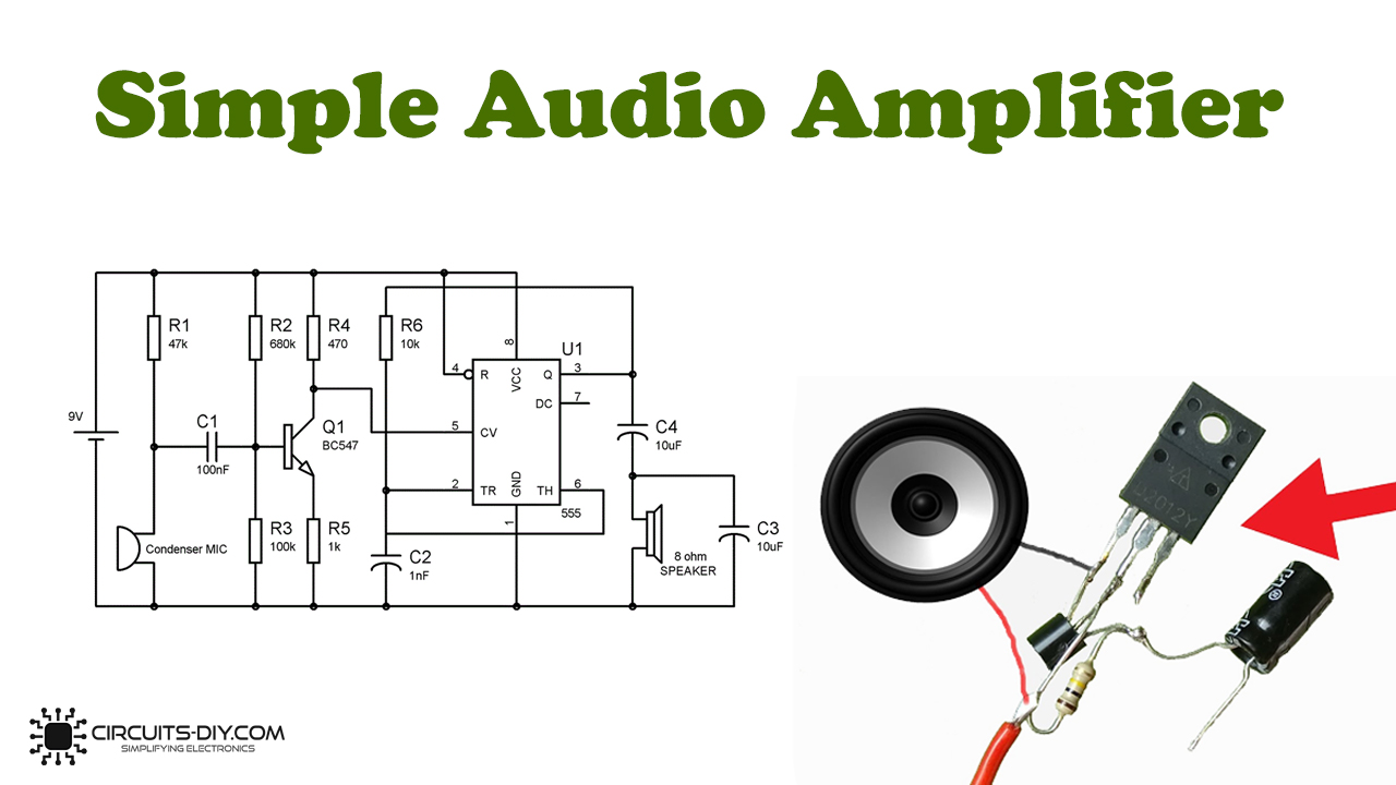
An electronics hobbyist is well aware of the importance, and use of the 555 timer IC in electronics projects. This is a versatile and powerful IC, it is likewise utilized in numerous small and big electronic projects. In this instructional DIY tutorial, we are going to perceive how a 555 IC utilizes as an Audio Amplifier. A low-intensity sound signal can amplify to a greater value by this circuit.
This circuit is partitioned into two sections: section one is the Preamplifier circuit, which comprises a BC547 semiconductor, a Condenser Mic, and a few resistors and capacitors. The second section comprises an 8ohm speaker and a 555 clock IC, which is swaying in Astable multivibrator mode, with approximately 66KHz frequency.
Hardware Components
The following components are required to make Audio Amplifier Circuit
| S.no | Component | Value | Qty |
|---|---|---|---|
| 1. | IC | NE555 Timer | 1 |
| 2. | Breadboard | – | 1 |
| 3. | Connecting wires | – | 1 |
| 4. | Battery | 9V | 1 |
| 5. | Capacitor | 10µF, 1nF, 100nF | 1 |
| 9. | Resistor | 1K, 10K, 47K, 100K, 680K, 470 ohm | 1 |
| 14 | Transistor | BC547 | 1 |
| 15. | Condenser Mic | – | 1 |
| 16. | Speaker | 8 ohms | 1 |
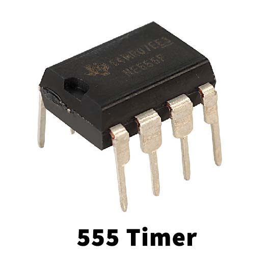
NE555 IC Pinout

For a detailed description of pinout, dimension features, and specifications download the datasheet of 555 Timer
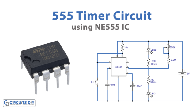
Audio Amplifier Circuit
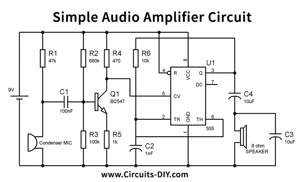
Working Explanation
The simple Audio Amplifier circuit appears in the above schematic. Control PIN 5 of 555, has been used here which is commonly kept grounded through a 0.01uF capacitor. Control PIN 5 is the purpose of 2/3Vcc inside the 555 timer IC, so we can change this 2/3Vcc voltage through this PIN. Furthermore, changing the voltage at this PIN changes the width of the output pulse, regardless of the estimation of RC parts in the 555 timer circuit. It follows a similar head of Pulse Width Modulation (PWM) to balance the yielding wave. We have utilized the usefulness of the Control PIN in this circuit.
Speaker doesn’t react to high frequencies, so when there is no voltage at control PIN 5, the speaker doesn’t deliver any stable sound signal. At the point when we make some sound close to Condenser Mic, that sound is changed over into an electric signal by the Transistor, and this electric signal is then transferred to the control PIN 5 of 555 IC. The yield pulse at PIN 3 tweak because of this voltage at the control PIN, and the speaker identifies this DC segment of the Output pulse and subsequently produces sound. Fundamentally when there is the voltage at PIN 5, the width of the yield pulse increments for a second, and that is distinguished by Speaker.
Resistor R1 is utilized for biasing of condenser Mic and R2 and R3 are utilized to give biasing to the semiconductor. We can test this circuit by blowing some air from the mouth towards the Mic, the speaker will start producing sound.
Applications and Uses
Important applications include:
- Public address systems
- Theatrical and concert sound reinforcement systems
- Domestic systems such as a stereo or home-theatre system.
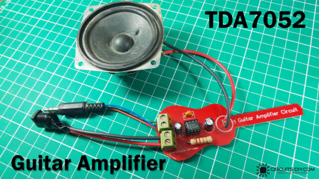
Additionally, Instrument amplifiers include:
- Guitar amplifiers
- Electric keyboard amplifiers
- Audio power amplifiers.