Introduction
Electronic code locks are very useful and efficient for security purposes and it has a high need since it offers great security. But not all electronic locks are effective and cheaper, some are not very efficient and some are very inexpensive. Digital code Lock using CD4013 which we are designing today is neither inefficient nor very expansive. Therefore, designers recommend this circuit.
The circuit is about the double flip flop, it uses two ICs and switch buttons which are used to enter the combination or code numbers. The relay only when the switches are pressed in the right combination is its code. The circuit should be built on a great quality board and must have 12V. The circuit should use an SPDT relay and Capacitor C1 must be of tantalum type.
Hardware Required
| S.No | Components | Value | Qty |
|---|---|---|---|
| 1. | Breadboard | – | 1 |
| 2. | IC | CD4013 | 2 |
| 3. | Resistors | 220ohms, 1.5K, 100K | 1, 1, 10 |
| 4. | Capacitors | 1uf, 100uf | 1, 1 |
| 5. | Switches | – | 8 |
| 6. | Diode | 1N4148, 1N4007 | 2, 1 |
| 7. | PNP Transistor | 2N3906 | 1 |
| 8. | Relay coil | – | 1 |
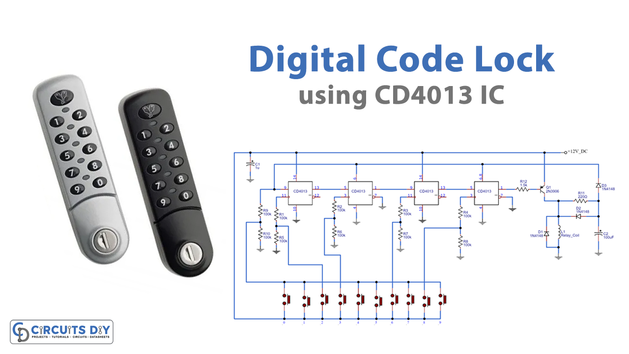
Circuit Diagram
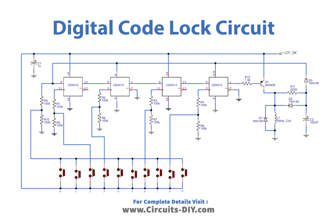
Working Explanation
Two CD4013 flip-flop ICs are used on this circuit. Switches are used to enter the code number. Here the code number is 2368 when the 2 is pressed the first flip-flop IC gets triggered and the value is given to pin 9 of the IC which is then transferred to the output pin 13 since pin 9 of the IC is grounded so the value will be 0, remaining code will be transferred in the same way and transistor gets ON when the 0 reaches the pin 1 and transistor make the relay ON. The time delay can be modulated by resistor R11 and capacitor C and as a result, the circuit works.
Application and Uses
- Firstly, in the security of banks, homes, museums, etc
- Similarly, it can help to make a secure home automation system
- Moreover, for security purposes of various machines and equipment