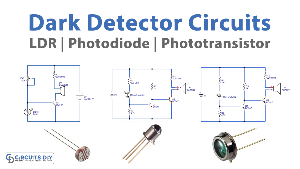
In this tutorial, we are going to make “Dark Detector Circuits using different Light Sensors”.
As we know that we always try to do and make things that save energy/power, a dark detector circuit can also help us in the same cause by automatically controlling and turning ON-OFF lights or any loads depending on the brightness of ambient light. For example, street lights; manually turning on those lights necessitates someone performing that task every day. On the other side, if we automate this process by employing a dark sensor that detects darkness and switches on automatically, we would save energy, power, and time.
Thus, there are different ways to make a dark detector circuit, all dark detector circuits are implemented with few easily available components and each circuit is designed to give an alert sound by the buzzer. You can use your application output actuator or microcontroller.
Based on the sensor and bias to the sensor output and sensitivity may vary, so you should calibrate before implementing the circuit into the application field.
Dark detector circuit using LDR
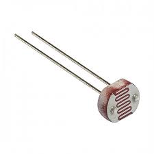
LDR (Light Dependent Resistor or Photo-Resistor). The resistance of LDR depends on the intensity or brightness of light incident on it and the relationship is of inverse proportionality. This means that when the intensity of light increases, the LDR’s resistance reduces and vice versa. This LDR element will have two terminals and one semitransparent CdS (Cadmium Sulfide) layer and the impurity semiconductor makes this device photosensitive depending on the light intensity. As we know the resistance of this device will vary depending on light, this character is used in many light-related applications.
LDR Symbol
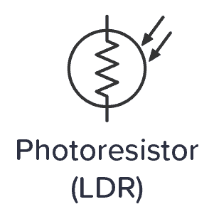
LDR – Light Dependent Resistor
Circuit Diagram
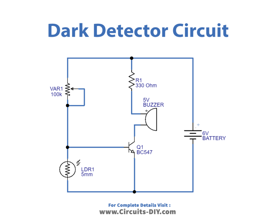
Working Explanation
In this circuit, small size LDR is connected to the power supply through variable resistor VR1 and then the transistor Q1 base is connected to the LDR pin and the buzzer is connected through the transistor collector terminal. Here variable resistor VR1 allows us to adjust the sensitivity level. When the light falls on the LDR it becomes less resistive and the transistor base doesn’t get supply and becomes in the cutoff stage which means there is no current flow across the circuit when a continuous light falls on the LDR when the LDR senses the darkness then it became as high resistance element and positive supply through variable resistor reaches the transistor base and transistor gets turn ON, the electricity begins to flow through the circuit. As a result, the buzzer starts to produce a beep sound.
Dark detector circuit using Photodiode
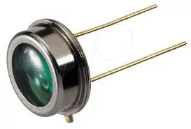
A photodiode is just like a regular semiconductor diode consisting of a p-n junction, but it has this junction exposed to light through a transparent body and releases electrons when receives photons. The photodiodecadmium-sulfide is an active light-detecting element and it controls the current flow this element depends on the light intensity. Compared to cadmium-sulfide or cadmium-selenide photocells like LDRs, photodiodes are generally less sensitive to light, but their response to light changes is much faster. Due to this reason, LDRs are generally used in applications that involve visible light, and where the response time does not need to be quick. On the other hand, photodiodes are specifically selected in applications that require fast detection of light mostly in the infrared region.
Photodiode Symbol

Photodiode
Circuit Diagram
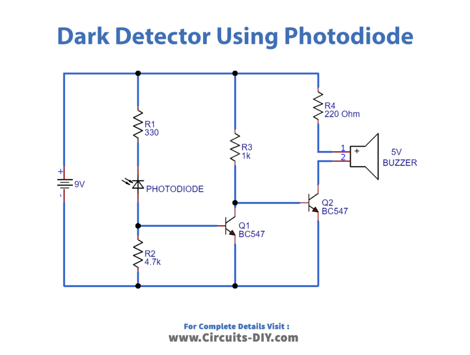
Working Explanation
When the photodiode is exposed to darkness, this may result in a current and the circuit produces a beep sound through the buzzer. Here R1 & R2 resistors are used to vary the sensitivity of this photodiode.
Dark detector circuit using Phototransistor
The phototransistor is generally in the form of a bipolar (NPN or PNP semiconductor layers separated by intrinsic or photosensitive semiconductor) silicon transistor encapsulated in a cover with a transparent opening. It is an active photosensitive device, that can control the current flow depending on the light intensity. It works by allowing light to reach the PN junction of the device through the transparent opening. The light reacts with the exposed PN junction of the device, initiating the photoconductivity action. A phototransistor is mostly configured with its base pin unconnected; it shows identical amounts of current at its collector and emitter pins, due to an open base connection, and this prevents the device from negative feedback.
Phototransistor Symbol
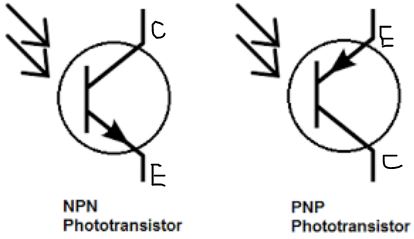
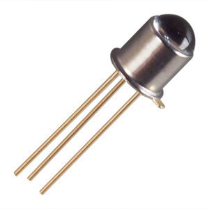
Phototransistor
Circuit Diagram
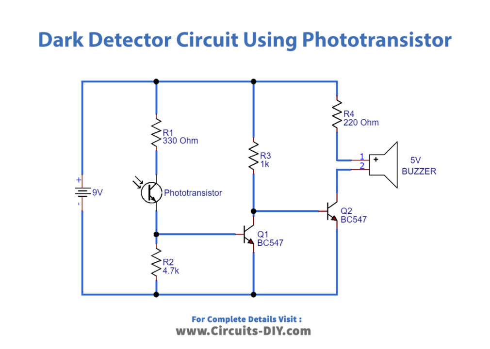
Working Explanation
When the phototransistor gets enough light Q1 will conduct and pull the base of Q2 to the ground. Q2 won’t conduct anymore and the LED will extinguish. If there’s less light than needed then Q1 won’t conduct, Q2’s base will get current through R3, and the LED will light up. R2 is there to make sure that Q1 won’t get current if it’s dark. R1 will limit Q1’s base current in case the phototransistor will want to source too much of it. This circuit will provide a beep buzzer sound when the phototransistor is exposed to the darkness, the sensitivity can be varied by changing R1 and R2 resistor values.
Applications
- We may utilize these types of darkness detector circuits in applications that automatically switch on lights when it becomes dark.
- We may use it as an emergency light in low-light situations.
- It is also accessible for mining employees.