Telephone line tester circuit is more like a meter. Also, it is a very simple circuit involving just few resistors, a switch and an ammeter.
Hardware Required
| S.no | Components | Value | Qty |
|---|---|---|---|
| 1. | Ammeter | 0-1mA | 1 |
| 2. | Resistor | 270Ω/1W , 27KΩ | 1, 1 |
| 3. | Variable resistor | 50KΩ | 1 |
| 4. | Switch | – | 1 |
| 5. | Telephone line | – | 1 |
Circuit Diagram
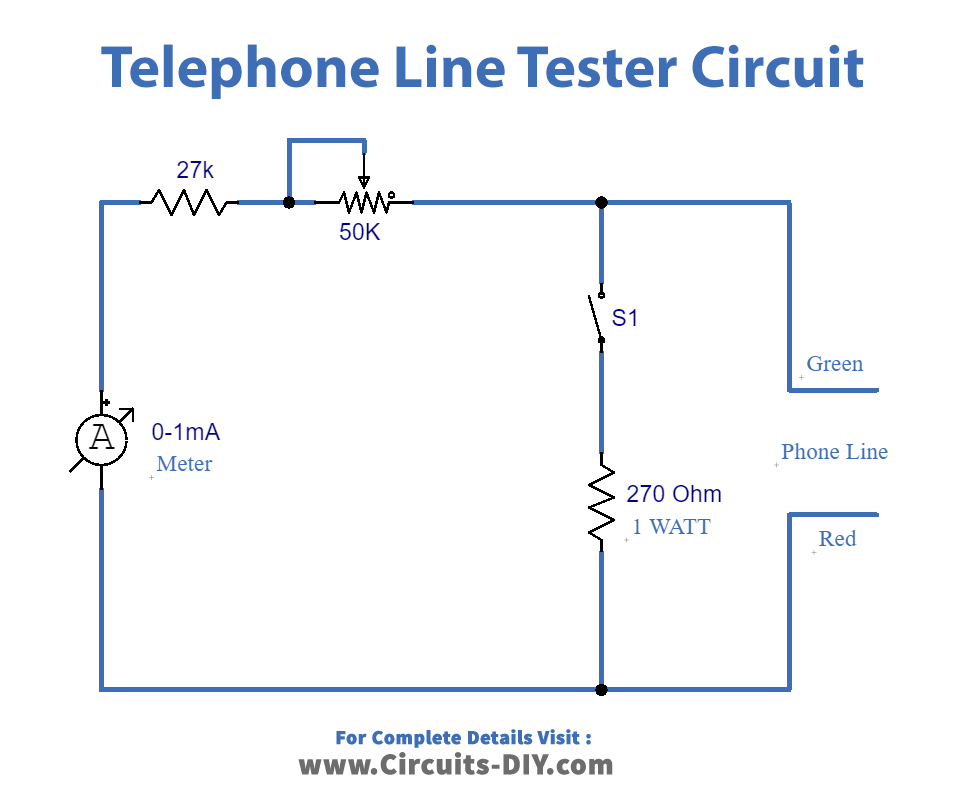
Circuit Explanation
Firstly, it is to be noted that the telephone line voltage does not remain same all the time. Thus, it changes when the receiver of the telephone is picked up. Also, the voltage changes with the ringing of the telephone. Therefore, in order to check whether the line’s properly working or not, this circuit is applied.
Secondly, the circuit arrangement is simple. It just requires some resistors and a 50KΩ variable resistor as shown in diagram. Hence, whenever there is a call on the line, the meter shows deflection. Thus, this indicates the proper working of the telephone. If deflection is not to be seen, then we’ll know there might be connection or line problems.
Application
- to test the setup of new lines