Introduction
Shortwave receivers are designed to detect radio frequencies that start from the AM broadcast band and go up to around 30 MHz. However, these general-coverage shortwave receivers do not detect many exciting and unique signals in the lower frequency range. A very Low Frequency (VLF) converter circuit solves this problem. This circuit can detect and convert the very low radio frequencies in the atmosphere to audible sound.
What is VLF?
VLF, or very low frequency, refers to wireless and electrical frequencies transmitted in the lower frequency range between 3 kHz and 30 kHz. A number of rare signals can be heard on frequencies below 15 kHz, including the dit-dah wave, which is slow and comes in two tones, and powerful lightning and electrical storms, which can be heard as crunching, whistling, and crackling noises before the thunderstorm strikes. On frequencies above 15 kHz, you can expect to detect various signals, including Loran, military signals, foreign broadcasts, and CW signals.
VLF Detector Circuit
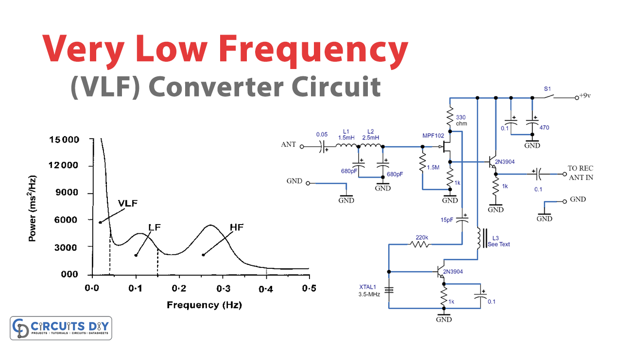
The VLF converter circuit can cover all very low frequencies or VLF from less than 10 kHz to above 260 kHz.
Hardware Required
| S no | Components | Value | Qty |
|---|---|---|---|
| 1 | MOSFET | MPF102 | 1 |
| 2 | Transistor | 2N3904 | 2 |
| 3 | Resistor | 1.5M, 220K, 15, 1K, 330 | 1, 2, 1, 3, 1 |
| 4 | Capacitor | 0.05, 680, 0.1, 15, 470pF | 1 |
| 5 | Inductor | 1.5mH, 2.5mH | 1 |
| 6 | L3 Inductor | — | 1 |
| 7 | Switch | – | 1 |
Circuit Design

The VLF detector circuit can be quickly built using the components shown in the circuit diagram, covering all very low frequencies from less than 10 kHz to above 260 kHz. To operate the circuit from 200 kHz to 500 kHz, you must exchange a few input-filter components and remove C2 and C3, substituting C3 with a 150 pf, 100-WVDC ceramic disc capacitor. You must also discard L2 and attach L1 to Q1’s gate. You can bridge the connections across L2 to construct a short-term change.
Construction Tips
- The components should be mounted on a 2 x 3-inch perf board or circuit board.
- Ensure that interconnecting leads are short and the crystal-oscillator circuit is isolated from the front-end circuitry.
- Use a socket for XTAL1 if you need to convert to another frequency.
- Enclose the converter in a metal case for optimal performance.
- Use a battery to power the circuit since it draws only a few milliamps of current.
- Connect the converter’s RF output to the shortwave receiver’s antenna via a shielded or coaxial cable.
- Connect a strong ground to both the converter and receiver.
- Use a reasonably long wire antenna and tune the receiver’s mode switch to the CW position.
- Be careful while constructing the circuit since it operates at low frequencies.
- Inductor L3 can be constructed by winding a 26-gauge wire 30 turns on a 0.25-inch diameter ferrite core retrieved from an old AM-radio loop stick antenna coil.
Testing the Circuit
To test the VLF converter, the receiver must generate a loud tone through its BFO (beat-free oscillator), heterodyning with the 3.5 MHz signal from the converter’s crystal oscillator. When the receiver is regulated above 3.5 MHz and moving towards the 4 MHz mark, the dial value, beginning from 3.5 MHz, can be utilized to scan the converted frequency.
Range Selection
We can diversify the range of the VLF converter by changing the crystal’s frequency and L1’s inductance. To swap from an 80-meter band to a 40-meter band, both the crystal and L3 should be replaced. We can alter the value of inductor L3 to function in the 40-meter band by unwinding around ten turns.
Final Words
In conclusion, the VLF converter circuit is a simple and effective way to detect and convert very low radio frequencies in the atmosphere into audible sounds. With the ability to cover a range of frequencies from less than 10 kHz to above 260 kHz, this circuit opens up a world of exciting and uncommon signals that are not typically accessible with general-coverage shortwave receivers.
While constructing the circuit, it is essential to follow the construction tips to ensure proper isolation and grounding. With a bit of tweaking, the VLF converter’s range can be diversified, making it a versatile tool for amateur radio enthusiasts. We hope you found this article informative and valuable. If you have any questions or comments, please share them below.